Welcome to ONGC Hazira Plant Intranet
MANAGEMENT OF CHANGE
INTRODUCTION:
A process industry is subjected to continuous modifications to achieve higher efficiency, improve operability and safety, improve reliability, improvement of the plant machineries and equipment and to accommodate technical changes.
ONGC Hazira Plant is a sour gas processing complex sprawling over 700 hectares and is built with the state of Art technology at a cost of Rs 1300 crores.The sour gas and associated condensate from South Bassein are brought to Hazira Plant by sub sea pipelines. The gas and condensate are treated to produce various products like LPG, NGL, Sweet Gas, SKO, ARN and Heavy cuts. Besides we have captive power plant designed to generate 57.6 MW power through 3 gas turbine generators which caters to the need of the plant and colony and the exhaust of the turbines are used for steam generation. There are specialized treatment units to treat different types of effluents in the plant as required by regulatory authorities.
Any changes in the processing units/facilities in the Hazira Plant may have the potential to introduce new hazards. That is why the hazards connected with any change are to be identified and controlled efficiently through an appropriate hazard assessment and mitigation system.
Why Change? :
The need of change arises out of the following reasons :-
- Operational flexibility.
- Energy conservation.
- Capacity augmentation
- Improvement of product specification
- Yield improvement.
- Compliance with Statutory rules and regulations concerning to safety, health & environment
Types of Changes to be taken into account :-
The various types of changes that may take place in Hazira Plant are :-
i) Equipment changes like addition, alteration or removal of an equipment or a part of it from the plant.
ii) Modifications in piping system and process equipment, replacement of equipment or machinery that differs from the original equipment.
iii) Change in normal operating procedure, start-up, shutdown and emergency handling procedures.
iv) Change in instrument which may include pressure, temperatures, flow, set points, alarm points, speed, logic and control parameters.
v) Induction of operation or maintenance personnel who are new in respect of the process.
Procedures to implement changes:
A. CHANGES DUE TO MODIFICATION OF PLANT /FACILITIES:
Operation Head will see that written procedures to manage change in facilities and personnel are established and implemented.
Procedures cover the following:-
1. Origination of modification proposal:
Any proposed change shall be considered critically on the basis of its necessity, techno-economical feasibility and search for a better alternative. The impact of change on the people and work environment will be examined on top priority.
Scrutiny of technical basis of the proposed change and modification of operating procedures shall be checked before finalizing the modification proposal.
2. Design Philosophy :
The design philosophy includes both process design information and mechanical design information. The process design information shall include a block diagram or a simplified process flow diagram.
The mechanical design information will include materials of construction, piping and instrumentation diagram (P&ID), design codes and standards employed and equipment and piping specifications.
3. Process Hazard Analysis:
Process hazard analysis is a systematic assessment of potential hazards associated with any new modification process to the existing facilities. Area managers will be responsible for initiating a PHA study of all modifications to be carried out in their area of control. Minor modification will be approved by Head Operations. For any major modification, IEOT will be contacted for the PHA study and it will be approved by GGM-Head Hazira Plant. Head operations will take a view and decide whether proposed modification is “Major” or “Minor”.
Head-Hazira Plant has constituted a four members multidisciplinary committee for assessment of introduction of new hazards through a systematic PHA. The members of the Hazard assessment committee are:-
1. Shri Subodh Kumar, DGM(E)
2. Shri Y. B. Sonar, CE(I)
3. Shri Siddharth Gupta, CE(E)-HSE
4. Shri T. K. Mandal, CE(P)
Hazard assessment committee, so formed, will adhere to the following guidelines:
a) Any impact of proposed changes on the health, safety and the environment.
b) Any impact on inspection and maintenance activities due to the proposed change.
c) The scrutiny of ‘the change’ so as to ascertain whether the change(s) are within the acceptable level of risk.
d) The aspect of operator’s training or involvement in making the change.
e) To propose necessary updation of documents in line with the proposed modification.
The hazard assessment committee will give necessary recommendations to the Head Operations.
As recommended by M/S ERS solutions Pvt. Ltd. vide No. MR/RO/MM/Third Party Audit/34/BB/2003-04/LT-33 in Chapter –V, the outcomes of PHA shall be shared with operators .
4. Scrutiny/approval procedure:
Detail engineering shall be done with the approval of Head operations. It shall be ensured that design is safe for expected conditions of use, environment and also unintended uses and misuses. These shall be confirmed with the detailed process hazard analysis by Hazard assessment committee.
5. Execution of the modification job procedures :
Modification shall be taken up for implementation only after availability of “Approved for Construction” documents and approval of statutory authority for the modification wherever applicable.
6. Training of operating/maintenance personnel :
The operating and maintenance personnel shall be trained properly for safe practices to be adopted after the proposed modification. Contract employees shall also be trained in proposed change prior to the start up of the process and
the start up review will be done. Any proposed change/modification shall be deliberated in the morning meeting held in Control Room building so that persons working in different areas can be well informed.
7. Commissioning:
Plants/facilities shall be commissioned after job carried out is cleared by multidisciplinary group approved by management and completion certificate is available.
8. Updating of Documents in line with modification:
Changes due to the modification shall be incorporated in operating and maintenance manuals, P&IDs, Layouts, PFPs and risk analysis report.
9. Handing over and Taking over :
Executing departments / agencies shall handover the facilities with all documents like manuals, drawings etc. to the operating departments properly.
10. Post Audit :
Safety check-list shall be prepared in view of the modification. A test run shall be conducted to evaluate the achievement of the objective of modification and the test results will be recorded.
11. As Built records:
Modification records such as design review, construction documents, statutory approval shall be preserved in approved and accepted locations for quick references.
12. Check-list for Management of change:
Any technical changes in the process operation like modification, up-gradation etc shall be done as per the guidelines provided in the check list of Management of change (OISD-178 check list).All concerned area managers will have the overall responsibility to see that the modifications/change(s) are carried out as per the said OISD guidelines.
B. ADDITIONAL CHECKS FOR CHANGE IN
Changes in normal operating procedure, start-up, shut down and emergency handling procedure resulting from any modification/change has the potential for disruption and hence requires careful considerations to identify incorrect assumptions and to eliminate inconsistencies.
Procedures to implement such changes covers the following:-
1. A written operating procedure shall be provided. The operating procedure shall include the changes/modifications that plant has undergone and specify sets of conditions within which the plant shall operate.
2. Clear instructions for safe operation will be given with process safety information.
3. Occupational safety, health and environment considerations such as properties and hazards presented by the material needed in the process special precautions to be taken and personal protective equipment & control measures to be taken if physical contact or air bone exposure occurs will be taken care of through training/demonstration of the concerned persons.
C. CHANGE OF PERSONNEL:
Induction of personnel who are new to the process may introduce new hazards. Hazira Plant has a systematic induction training programme for the new personnel conducted by Training Centre.
1. Each new personnel shall be trained in an overview of the process operating procedures and maintenance.
2. The training shall include emphasis on the specific safety and health hazards, emergency operations, use of personal protective equipment and handling of emergency.
D. ADDITIONAL CHECKS FOR INTRODUCTION OF NEW CHEMICALS, CATALYST AND CORROSION CONTROL AGENTS:
Change in chemicals, corrosion control agents and catalyst is normally done to accommodate technical innovation, increase in efficiency and cost benefits.
Procedures cover the following:
1. A written procedure for handling of above materials shall be provided to concerned personnel.
2. Material safety data sheets shall be provided.
3. Procedure for catalyst regeneration and disposal of spent catalysts shall be provided.
E. ADDITIONAL CHECKS FOR CARRYING OUT CHANGES OF LOGIC OF INTERLOCKS SET POINT AND PROCESS CONDITIONS:
Procedures cover the following:
1. Instrument & Process Engineering shall check the existing ladder diagram whether the intended change can be incorporated.
2. Hazard assessment committee shall conduct a HAZOP study of the scheme proposed for change.
3. The committee will examine whether modification in logic can be incorporated in running plant or the plant has to be shut down. If it requires shut down of the plant, the downtime loss and payback period after modification shall be studied.
4. The HAZOP study recommendation shall be approved by Head Operations based on the approved scheme, detailed engineering drawing shall be prepared.
5. The changes shall be incorporated in the ladder diagram and operating manual.
Handing Over of Charge:-
Hazira Plant follows procedure for handing over of charge based on the enclosed organograms.
Methodology adopted for handing over of charge in different level of operations is as below:
A. Sectional Heads/ Area Managers :
During the absence of any sectional Head /Area Manager, the next senior most executive of the concerned sections / areas looks after the duties of Sectional Head / Area Manager In addition to his own.
B. Process Shift Operation:-
Shift Operations of continuous Process Plant of Hazira is one of the vital activities and it includes monitoring of receipt of sour gas / condensate, processing to value added products and storage & dispatch etc. Proper supervision and monitoring of each and every activity is required for safe operational practices.
In view of above fact ,deployment of human resource at the right time in the absence of any personnel is of paramount importance.
1. DGM(P),In-charge shift Operations:
During the absence of DGM (P) Incharge shift operations, CE(P)-Process ,the next senior most officer looks after the duties of the DGM (P) In- charge, Shift Operations.
2. CE(P)-Process:-
During the absence of CE(P) process, the next senior most CE(P)-Overall shift In charge takes the charge of CE(P)-Process.
3. Overall shift Incharge-CE(P):-
In the absence of CE(P)-OSI, next senior most SE(P)- Shift In charge looks after the duties of OSI.
4. Shift-Incharge :-
During the absence of shift-in-charge, senior most officer of the concerned shift takes the charge of the shift In-charge.
5. Shift Personnel:-
In the absence of any Shift Personnel, the suitable persons of the concerned shift based on relevant experience and skill is placed for the specific job as decided by OSI/SI on day to day monitoring basis.
OISD – 178
ANNEXURE – I
CHECK – LIST FOR MANAGEMENT OF CHANGE
1. Initiation for modification / change.
2. Approval by competent authority notified by the local management.
3. Process design philosophy.
4. Review in engineering practices / safety, health and environmental impact.
5. Process hazard analysis.
6. Scrutiny and approval procedure.
7. Preparation of detailed engineering drawing for execution.
8. Construction activities for the proposed change.
9. Pre-commissioning check by multidisciplinary group.
10. Training of personnel.
11. Commissioning.
12. Post-commissioning review.
13. Handing over, taking over procedure.
14. Updation of documents like PFD, P&ID and process & operating manuals.
15. As-built records.
ANNEXURE-II
Pre-Start up Checks after Turn around of Process units/facilities
Unit : Date of checking : __________
Sl. No. | Items to be Checked | Checked Yes/No |
1. | All the Hydro-test blinds are removed. | |
2. | All flanges are boxed up with correct rated gaskets. | |
3. | All control valves, other equipments like level, pressure & Temp. switches etc are online. | |
4. | All hydrocarbon and H2S Gas detectors are on line. | |
5. | All LGs, LTs, PTs & FTs etc. transmitting impulse tubing are properly connected with no loose tube fittings. | |
6. | All thermo wells are boxed up. | |
7. | All correct PSVs are lined up. | |
8. | All open vents and closed drains are either closed or blinded. | |
9. | All temporary hose connections which were fitted during shutdown are removed. | |
10. | All the pipe line blinds which were fitted / removed during isolation are fitted with proper spacers before hydrocarbon entry. | |
11. | Oil level checked for bearing in the HT motors. | |
12. | The units are properly inertized and system fit for gas intake. | |
13. | All the control valves are stroke checked and rectified for mis-match. | |
14. | Leak check of the system is performed using inert gas at the available pressure. | |
15. | All sampling and draining points are properly closed / isolated. | |
16. | Coupling guards of all compressors and pumps are fitted. | |
17. | Earthing connections are checked and are OK. | |
18. | Checking of modules and mongering from substation ends are done. | |
19. | All Flame proof fittings are checked and OK. | |
20. | All lockouts are released and lock out permits closed. | |
21. | All un-necessary scaffoldings and wooden planks are removed (except few for further job, if any). | |
22. | The unit area is free from all obstructions. | |
23. | All necessary safety instruction boards are in place. | |
24. | All fire extinguishers are in their original places. | |
25. | Eye wash showers are working. | |
26. | All life saving equipments are in their original places. | |
27. | All the water sprinklers on pumps and other equipments are in line. | |
28. | All the steam hoses and compressed air hoses are in their places and not lying on ground. | |
29. | All nitrogen trailers, maintenance tools, contractor’s equipments are removed. | |
30. | Over all House keeping is adequate. |
List of Pending items to be made Ok before actual Start-up :
1.
2.
3.
4.
5.
The unit is fit for start up and all aspects mentioned above are checked and found OK.
1. Operation Name & Signature:
2. Mechanical Maintenance Name & Signature:
3. Electrical Maintenance Name & Signature
4. Instrumentation Name & Signature:
5. HSE Name & Signature:
LIST OF MINOR MODIFICATIONS MADE
A. GAS SWEETENING AND GAS DEHYDRATION UNITS :
1. Automatic pressurisation of Regenerator of GSU train 31 with fuel gas:
The system was installed in Feb’2000. Schematic diagram is placed at Sl. No. 1
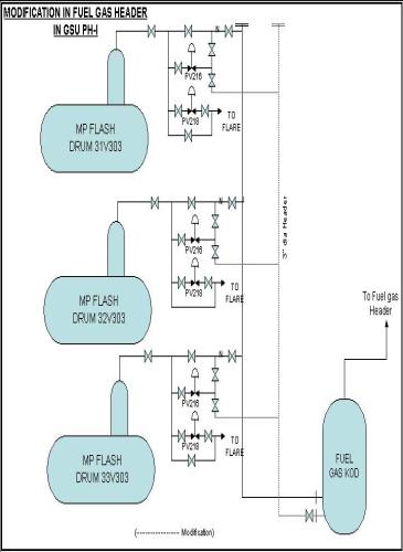
2. Modification in fuel gas header of MP flash drums in GSU-I trains:
Fuel gas lines from MP flash drums of trains 31, 32 and 33 have been augmented by laying an additional 2” header. This is to avoid back pressure on MP flash drums and subsequent flaring. The schematic diagram is placed at Sl No. 2
3. Modification for minimum flow for MDEA injection pump in GSU I and II:
A minimum flow provision to the MDEA injection pumps of GSP Ph-I and II has been made through 4” of control valve. The schematic diagram is placed at Sl. No. 3.
4. Sweet gas pressurising to GSU trains of Phase-I and II.
One 4” sweet gas line from DPD outlet (at tap-off point for fuel gas to co-gen) has been laid down joining GSU inlet of Ph-I and II. This is for pressurising and leak test of the trains. Schematic diagram is placed at Sl. No.4.
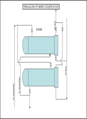
5. Paralleling of Amine Coolers E302A/B of GSU Phase-I and II trains:-
Modification carried out in Sept”2001.Cooling water line to Amine coolers (E 302A/B) has been modified for operation in parallel as well. This enhances the heat duty.
Schematic diagram is placed at serial no 5.
6. Rerouting in fuel gas system of GSU/GDU of Phase-I and II trains through suction KOD of vapour compressor:
Commissioned in June’2001.Fuel gas generated in GSU trains were routed through KODs installed in GSU trains of Phase-I and II which were of very small capacity (0.65M3). The fuel gas generated in GDU trains was directly joining the fuel gas header from degasser itself. Because of smaller capacity of KODs/direct routing of fuel gas from GDU trains, heavy carryover of liquid was observed whenever there was any operational upsets in either GSU of GDU trains. The total fuel gas header used to get filed up with liquid and affecting downstream consumers of fuel gas like KRU, boilers and incinerator. Due to carry over problem these units sometimes had to be shutdown.
In order to avoid recurrence of the above problem, it was thought of installing higher capacity KODs in the fuel gas streams of Ph-I and II.. The vapour compressor system installed along with GSU trains of Phase-I and II trains are not in operation since last 10 years. Each train is having two numbers of KODs installed at the 1st and 2nd stage suction of vapour compressor. They are designed for 7.5 Kg/Cm2 and 1430C, which are suitable for fuel gas system. Also there are 26.5 M3 capacity which is much higher than existing KOD.
Suitable modifications in fuel gas system have been done by rerouting the fuel gas from Ph-I GSU trains through V306 of train 33. Similarly the fuel gas from GDU trains of Ph-I are routed through V305 of train-33. The out let of these two vessels are combined before it joins the common fuel gas header. In addition the liquid out let of V305 is connected to pure TEG header to recover TEG. Provision exists in V306 for recovery of MDEA. The vessels contain PT, LT, LG, level switches for high and low to monitor the operating parameters. The vessels are having two numbers each of safety valves set at 7 Kg/cm2.
On the same lines, the fuel gas system of Phase-II also modified through the vessels V305 and V306 of train 34.
The modified drawings is enclosed at serial nos. 6 and 7..
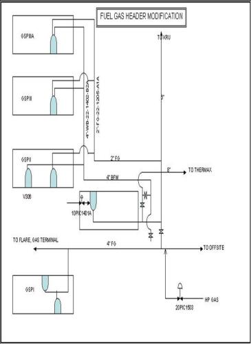
7. Modification in Fuel Gas Header:
The fuel gas generated from MP flash drums of GSP units are connected to main 10” FG header. The supply header from GSP Ph-II, III and IIIA are of 2” size.since the 2” header could not handle the total fuel gas, redundant 4” boiler feedwater header is used as an additional header from GSP Ph-II, III and IIIA to the main FG header behind LPG recovery unit. The necessary modifications were done and the header was commissioned in May, 2002.
The relevant drawing is enclosed at sl no 8.
8. Relocation of
LV1116 of GDU trains 46 and 47 of Phase-IIIA were relocated, away from feed nozzle to regenerator. This is for avoiding flashing near feed-nozzle, which may cause liquid carry over.
The relevant drawing is placed at serial no 9.
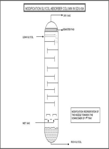
9. Modification in H.P. Glycol Absorber of GDU-IIIA.
Gas feed nozzle was modified by re-orienting the nozzle towards downcomer of 1st tray of absorber. The top bubble cap tray has been made dry. This modification has been done to minimise glycol loss.
The schematic diagram is placed at serial no 10.
10. Modification of 31 LV112:
31LV112 has been modified to take care of high pressure drop by replacing it with 71LV106 in June’2000.
11. Primary reduction valves (PV1101) at GSU inlet of trains 31, 32 and 33 which were of smaller size (6”) has been replaced with 12” size. This helped in reducing pressure drop. Earlier 6” size were suitable for high pressure case where pressure drop envisaged was 18 Kg/cm2. High pressure conditions were never operated so far.
B. DEW POINT DEPRESSION UNITS :
1. Modification of Propane Make Up line:
This modification was carried out in 51 and 52 trains to carry out the propane make-up to Gas Chiller (E-502). This helped in reducing the make up time due to larger differential pressure available between Propane storage and chiller. This helped in avoiding the operation of Propane transfer pump. The possibility for flaring of propane from accumulator where propane make up was being taken earlier was also avoided.
Process flow diagram is placed opposite at serial no 11.
2. Modification for By-pass of DPD Ph-I and II and DPD gas to Cogen Plant :
One 12”, 600 # bypass line to DPD Ph-I and II was installed with 8” butterfly pressure control valve. These modifications were carried out to supply of gas to HBJ line temporarily during shut down of DPD-I and II. However, high hydrocarbon dew point has to be taken care of by M/s.GAIL during this period.
The PFD is enclosed at serial no 12.
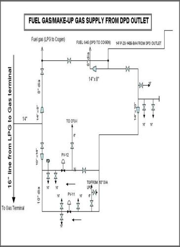
3. Supply of DPD outlet gas to Local Consumers/IPCL:
A facility to supply DPD outlet gas to local consumers (now IPCL, Dahej) has been created as a make up to lean gas.
The schematic diagram is placed at serial no 13.
C. CONDENSATE FRACTIONATION UNITS :
1. Condensate of Flare Knock out to NGL tank :
The condensate of Flare Knock out drum of CFU is originally routed to SLOP tank in offsite area. This condensate was found suitable for storing in NGL tank. An interconnection between SLOP tank line and NGL line headers was made near caustic wash unit. This facilitates the storing and despatch of condensate as NGL.
2. Modification in Trains 72 and 76 :
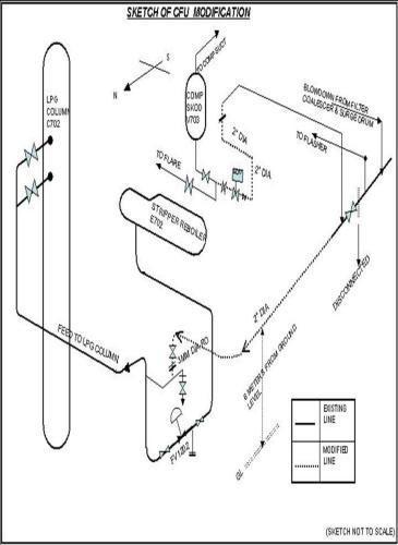
Modifications have been carried out for recycle of Hydrocarbon liquid from off gas suction KOD of CFU trains 72 and 76 to LPG column C-702 for recovery of value added products. The modification of Tr-72 was carried out in Oct’2001 and Tr-76 In Oct’2002.
The brief is as below:
Sour condensate from offshore is processed in CFU trains for stripping of the H2S and then fractionate the same to recover LPG and NGL. This stripped off gas known as CFU off gas passes through a suction KOD (V703) where most of the condensable hydrocarbon gases are knocked out in the form of liquid. The off-gas from condensable vapours is then compressed and routed to GSU. The liquid hydrocarbon condensate accumulated in the suction KOD used to be flared for want of suitable recovery system.
To recover the KOD condensate, a 2” dia and about 30M line was laid from the bottom drain line of the KOD. This line joins the feed line to LPG column from stripper reboiler at the downstream of the control valve FV1202 adjacent to the sampling point. An SDV, operable from the main control room was installed on the line nearer to the KOD.
The above modification thus enabled recovery of the suction KOD liquid in the LPG column and reduction of flaring from CFU.
Relevant sketch is placed at serial no 14.
E. SULFUR RECOVERY UNITS :
1. Inverted U-
2. Arrangement of Sump basket at the common suction of the Slurry Pumps to avoid damage to the rotary equipment.
3. Modification of Locat Return Line. The schematic for the above three is placed at sl no. 15.
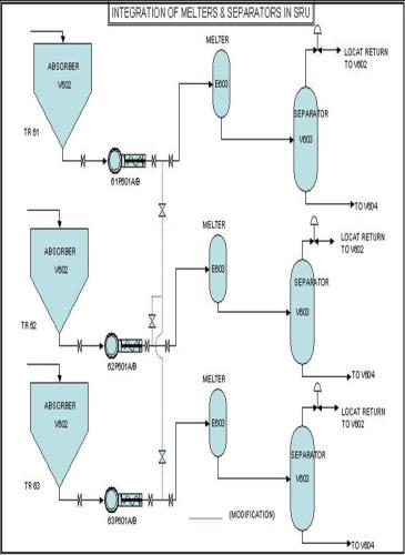
4. Integration of Melters and Separators :
Integration of Melters and Separators – This facilitates the flow of slurry from any of the oxidizer to any of the melter and separator of the unit. However, this is being practiced in Ph-I trains separately and Ph-II, III trains separately due to high pressure drop and chances of line choking. The schematic is placed at sl no 16.
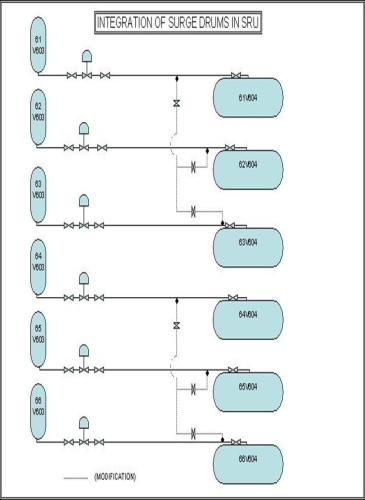
5. Integration of Surge Drums :
The Surge Drums of all trains are integrated. This facilitates the storage of molten sulfur produced from any of the trains, into any of the surge drums. Normally molten sulfur produced from all Ph- I trains is stored in one surge drum (61/62/63 V604) and from Ph- II & III trains in another surge drum (64/65/66 V604). The schematic is at sl no 17.
6. A horizontal centrifugal pump was installed outside the surge drum of train 61 for transferring the molten sulphur inside the surge drum to palletising unit. The earlier vertical pump inside the drum was non-operational and difficult to maintain/repair.
7. Modification for Venting off SRU sump gas:
Modification for venting off SRU sump gas – The vent gas of SRU underground sump has been connected to flare through flare KOD of DPD – I. This is done to reduce back pressure on sump so as to release the vent gas. This facilitates smooth draining of Acid Gas KODs. The schematic is placed at sl no 18.
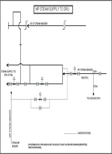
8 MP steam supply to SRU:
MP steam supply to SRU – Provision for supply of steam to SRU from MP steam Header has been made in case LP steam from LP steam header is not available. Schematic is at sl no 19.
9. Steam condensate recovery system:
Steam Condensate Recovery System – Steam condensate recovery system was installed in Oct 2001 and modified in Nov 2003. Steam condensate from plant is fully recovered and sent to Co-gen plant. The schematic is at sl no 20.
F. MODIFICATIONS IN LPG PLANT:
1. Installation of third LPG Dryer:
Third LPG Dryer will be installed in LPG plant to enhance gas processing capacity and operational flexibility. A hook up connection in existing pipe network has been completed. The job is under implementation and scheduled for completion in May’2005. The line diagram of hook up connection is placed at Sl.No.21 and 22.
2. Installation of flow meter in Propane make up line:
The schematic diagram showing propane make up line is placed at sl.no.23. Meter is installed in May, 2004. Cable connection is yet to be completed.
3. Piping modification for LP Kribhco Metering:
The schematic diagram is placed at serial no 24. The system is functional.
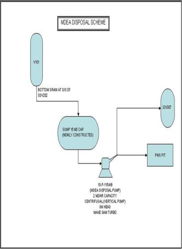
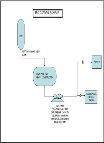
4. Modification for safe disposal of spent TEG and MDEA.:
The modification for safe disposal of MDEA from Inlet suction KOD (V101) of LPG plant and TEG from condensate surge drum (V115) has been done. For this purpose two no of sumps have constructed for safe disposal to PWS pits. The system is functional.
The relevant sketches are placed at serial nos. 25 and 26.
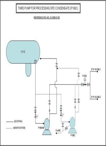
5. Installation of third condensate transfer Pump:
Third condensate transfer pump P106C was installed for processing of DPD condensate in LPG plant.
The schematic diagram is placed at serial no. 27.
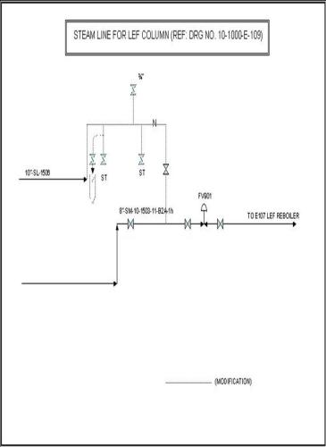
6. LP steam line connection for LEF column :
LP steam line connection has been provided in LEF reboiler as an additional facility over MP steam connection for operational flexibility in case of any problem in MP steam supply.
The schematic diagram is placed at serial no. 28.
7. Provision for MP gas supply to Local consumers:
This modification was done for supply of MP gas to consumers through Essar line .The supply network is at gas terminal. The schematic diagram is placed at serial no 29.
The supply MP gas to Essar is discontinued since March,2002 as HP gas is supplied to IPCL,Dahej.
G. MODIFICATIONS IN KEROSENE RECOVERY UNIT:
1. Provision of IG blanketing in Naphtha and Kerosene reflux drums (V902 & V903 respectively) retaining the facility by Fuel gas also.
2. Routing of “off spec” kerosene (SKO) to NGL tank by using NGL reprocessing line.
3. Converted P906A (Flare KOD pump) into Naphtha reflux/product pump to operate in parallel to P902 A/B.
5. Converted E911 (unused exchanger) into Heavy Cut Cooler in parallel to E902.
6. Converted V906 into IG buffer vessel.
7. Installed a pump P902C in parallel to P902A/B to take additional load of Naphtha reflux/product.
8. Installation of MP Steam System for preheating of NGL in KRU plant
MP steam exchanger (E912) in parallel to E902 as a NGL feed preheater to take care of 20% load of E902. A condensate pot has also been installed. The P&ID is enclosed alongwith schematic of modifications at sl no 30.
9. Installation of Dosing System :
Installed dosing system for improving conductivity of ATF in KRU plant. This system is presently being used for dosing of stabiliser for HSD production. The piping and Instrumentation diagram is enclosed at sl no 31.
10. Modification of 2 Nos. SKO tanks for storage of ATF.
Two SKO tanks were modified (piping system only) for storage and dispatch of ATF. The P&ID of the modification is available with concerned unit in charge.
.
11. Installation of Fuel Gas KOD:
Installed one fuel gas knock out drum to drain out any liquid carryover before end use in KRU plant.
H. MODIFICATIONS IN OFFSITE, WWTP, UTILITY AND OTHER AREAS :
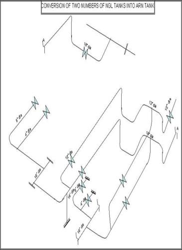
1. Conversion of two Nos. of NGL tanks to ARN tanks.
2 Nos. NGL tanks viz. C2 and D2 of Phase-II have been modified (piping modification only) for storage and despatch of ARN. The sketch is placed at Sl.No 32. Details of work carried out are as below :-
a) A separate 12” Header was laid for receiving ARN.
b) A separate 16” Header was laid for despatch of ARN.
c) 4 Nos tappings were provided.
i) One 16” tapping in the inlet of the Tank “C2” for receipt of ARN.
ii) One 16” tapping in the inlet of the Tank “D2” for receipt of ARN.
iii) One 12” tapping in the ARN receipt line from KRU.
iv) One 16 tapping in the suction line of pump P218A.
2. Provision of Header to receive LPG production in Phase-II Spheres.
Modification for provision of Header to receive LPG production in phase-II spheres from caustic wash unit was done in 2002.
The above modification was carried out for making Ph-I and Ph-II spheres independent with respect to LPG receipt and despatch. The schematic pipeline diagram is placed at serial no 33. The details of modifications are as below :-
a) As mentioned in the sketch a spool between two 4” valves was removed and equal tee branch was installed with valve in all 5 trains of caustic wash unit.
b) 4” branch line erected and connected with two 6 “ headers.
c) These two nos. 6” header was connected with 8” header which was erected from caustic wash unit up to the Ph-II LPG spheres where in 6” branch line connected as mentioned in the sketch.
d) One TSV size ¾”x1” was installed on 8” line in Ph-II spheres and outlet of TSV connected with existing 2” header.
3. FACILITY FOR LPG TRANSFER TO BPCL DEPOT:
Facility for transfer of LPG from LPG spheres to BPCL bottling plant has been created with the installation of additional pumps adjacent to phase II spheres area and dedicated line from pump manifold to BPCL depot by BPCL.
The related P & ID is enclosed at sl no 34.
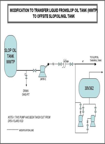
4 Modifications in WWTP :
Modifications for transfer of liquid from SLOP oil tank of WWTP to offsite SLOP oil tank has been done and the sketch is placed at serial no 35.