Welcome to ONGC Hazira Plant Intranet
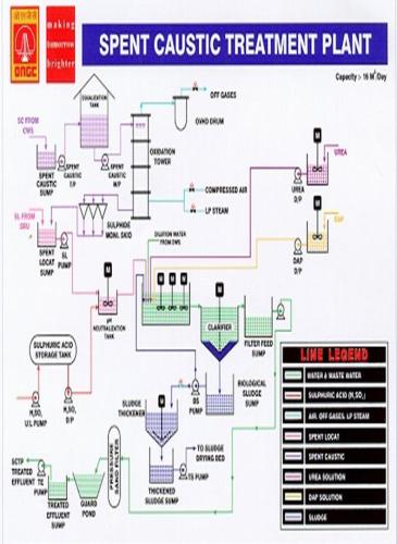
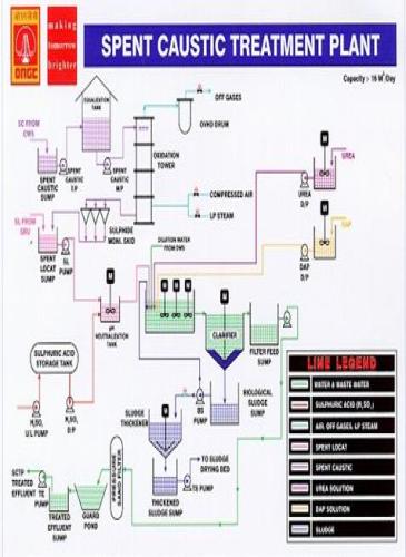
SPENT CAUSTIC TREATMENT PLANT
CONTENTS PAGE NO.
1. INTRODUCTION
DESIGN DETAILS 1
UTILITY REQUIREMENTS 2
MATERIAL BALANCE 3
2. PROCESS DESCRIPTON 4
3. BIOLOGICAL TREATMENT 7
4. STARTUP OF BILOGICAL TREATMENT SECTION 10
5. OPERATION OF EQUIPMENT AND UTILITIES
SPENT CAUSTIC SUMPS AND PUMPS 11
LOCAT SUMP AND PUMPS 12
pH ADJUSTMENTS AND TANKS 13
CLARIFIER 15
FILTER FEED SUMPS AND PUMPS 16
SAND FILTERS 16
BACKWASH SUMP AND PUMPS 17
GUARD POND 18
TREATED EFFLUENT SUMP AND PUMPS 18
BILOGICAL SLUDGE SUMP AND PUMPS 18
SLUDGE THICKENER 19
THICKNED SLUDGE SUMP AND PUMP 19
6.PLANT STARTUP AND SHUTDOWN
OXIDATION TOWER 20
NORMAL SHUTDOWN 25
EMERGENCY SHUTDOWN 26
7. CHEMICAL HANDLING SAFETY NOTES 27
8. PUMP OPERATION
CENTRIFUGAL 30
SCREW PUMP 30
METERING PUMPS 32
DESIGN DETAILS
Sl.N | Parameter: Stream : A | Parameter: Stream: B | ||||
A. | Spent Locat Soln | Composition (wt % ) | Pollutant Load Kg/day | Spent Caustic Solution | Composition (Wt %) | Pollutant Load Kg/day |
1. | K2S2O3 | 25.1 | 4217 | NaOH | 4.8 -7 | 215.3 (Na2S2O3 ) |
2. | K2CO3 & KHCO3 | 8.5 | 1428 | NaHS | 0.15-2.9 | 367.5(NaOH) |
3. | Fe ( Fe+ +, Fe+ ++ ) | 0.04 | 6.7 | Water | Balance | |
4. | Organics | 0.34 | 57.1 | ( Prior to its treatment in Air Oxidation Package) | ||
5. | Sulphur | 0.01 | 1.68 | |||
6. | Water | 66.0 | ||||
7 | Flow | 11.1(Max) m3/day | 5 ( Max) m3/day | |||
8 | Specific.Gr | 1.5 | 1.05 | |||
Characteristics of Treated Spent Caustic Stream from Air Oxidation Package | ||
Sl.N | Parameter | |
1. | Flow | Maximum: 5 m3/hr |
Minimum: 2 m3/hr | ||
Normal: 3 m3/hr | ||
Na2S2O3 | 215.13 kg/day | |
NaOH | 367.5 Kg/day | |
Water | 4566 kg/day | |
Sl.N | Nature | Flow Condition |
1 | Spent Locat Solution | Normal : 500 kg/hr - 12 T/day |
Minimum: 200 kg/hr - 4.8 T/day | ||
Maximum: 700 kg/hr - 16.8 T/day | ||
2. | Spent Caustic Solution | Intermittent flow* |
Normal: 3 m3/day | ||
Minimum: 2 m3/day | ||
Maximum: 5 m3/day |
* This waste water is drained into the inlet sump once in weekly/fortnightly basis. The capacity of the receiving sump is 10m3
Spent Caustic Treatment outlet characteristics | ||
Sl.N | Parameter | Treated effluent Standard at Outlet |
1. | pH | Not to exceed 6.5 to 8.5 |
2 | Oil & Grease | ,, 10 mg/l |
3 | BOD | ,, 15 mg/l |
4 | COD | ,, 100 mg/l |
5 | SS | ,, 20 mg/l |
6 | Phenol | ,, 1 mg/l |
7 | Sulphide | ,, 0.5 mg/l |
UTILITY REQUIREMENTS:
Design conditions of 5 m3/day (218.75 Kg/hr at S.G. 1.05)
Air for Oxidation 38 Kg/hr
L.P Steam 12 Kg/hr
H2SO4 20 Kg/hr 98%
Composition of Oxidised Caustic:
Na2S2O3 8.05 Kg/hr
Na 2 SO4 0.9 Kg/hr
NaOH 15.3 Kg/hr
H2O 187.5 Kg/hr
Composition of Off-gas
O2 4.4 Kg/hr
N2 30.0 Kg/hr
H2O Vapour 21.0 Kg/hr
Composition of neutralized Oxidised Caustic:
Na2S2O3 8.05 Kg/hr
Na 2 SO4 28.05 Kg/hr
H2O 191.0 Kg/hr
Theoretical Oxygen required for oxidation of Bisulphides to thiosulphates is
6.34 x (64/112) = 3.62 Kg/hr
Na2S2O3 produced =(6.34 x 0.9 x 64) / 112 = 8.05 kg/hr
Na 2 SO4 produced = (6.34 x 0.1 x 64) / 112 = 0.9 kg/hr
H2O produced = (6.34 x 18) / 112 = 1.02 Kg/hr
Due to allowance for tower efficiency and engineering factors actual air requirement is:
(3.32 x 2.2 x 100) / 21 = 37.92 Kg/ml ( say 38 Kg/hr)
comprising O2 = 8.0 Kg/hr
N2 = 30.0 Kg/hr
At 5.2 Kg/cm2 A and 1210 C :
Oxidation air volume = (38/28.9) x 22.4 x (394/273)x (1/5.2) = 8.17 m3/hr
Oxidation tower design:
Required specific air rate : 7-8 m/min
Nearest tower size is 500 mm dia
Sulphide oxidation rate: 3-3.5 Kg/m3/hr
Hold up volume:( 6.34 /3.5)x (1/81) m3
Tower height to normal liquid level 9.23 m approx.
Heat balance to normal liquid level 9.23m approx.
Temp0C
Rate In Out
Spent caustic feed 218.5 45
Oxidised Caustic 211.7 121 67
T = (211.7 x ( 121 -67) + 218.75 x 45) / 218.75 = 97.30C
Allowing for heat loss and fouling factor etc. say 950C.
SPENT CAUSTIC OXIDATION UNIT MATERIAL BALANCE; (DESIGN):
Component | Spnt Caustic Feed Kg/hr | Plant Air Kg/hr | LP Steam Kg/hr | Treated Effluent Kg/hr | Off Gas Kg/hr | Sulph Acid Kg/hr | Effluent Neutralised Kg/hr |
NaHS | 6.34 | ||||||
Na2S2O3 | 8.05 | 8.05 | |||||
Na 2 SO4 | 8.9 | 28.05 | |||||
NaOH | 15.3 | 15.3 | |||||
Water | 197.1 | 12.0 Nor 20.0 Max | 187.5 | 21.0 | 198.9 | ||
H2SO4 | 20.0 | ||||||
Oxygen | 8.0 | 4.34 | |||||
Nitrogen | 30.0 | 30.0 | |||||
TOTAL: Kg/hr | 218.75 | 38.0 | 20.0 | 211.7 | 55.3 | 20.0 | 227.0 |
Sl.N | Chemical | Quantity ( Kg/day) | Quantity (M.T / 6 Months) |
1 | Sulphuric acid | 1573 | 283.14 |
2 | MgSO4 (100%) | 29 | 0.36 |
3 | Urea (100%) | 105 | 18.9 |
4 | Phosphoric Acid | 37 | 6.66 |
5 | Polyelectrolyte | 0.5 | 0.09 |
PROCESS DESCRIPTION
Spent Caustic treatment plant is designed for the treatment of very concentrated streams which contains high oxygen consuming compounds like thio-sulphate, organic matter as well toxic constituents like sulphides, which when discharged untreated even in small quantities, would harm aquatic & human life.
The process can be divided into two different sections:
1. Wet-Air oxidation process
2. Biological treatment section.
Wet-Air Oxidation process:
The purpose of the Spent Caustic Oxidation Unit is to remove, by oxidation, the obnoxious bisulphates in the Spent Caustic streams.The sulphidic material is converted primarily to thio-sulphate, approximately 10 % going to sulphate, both of which are water soluble and remain in the effluent stream. The thio-sulphate has a much lower and longer term oxygen demand than the sulphide or bisulphide, and can be discharged without any serious hazard to marine life. However, in this package, the oxidized and neutralized spent caustic is further treated in the biological treatment plant to reduce COD to 100 mg/l
The streams treated in the unit are:
1. Spent caustic from LPG and NGL units
2. Spent caustic from sulphur recovery unit.
Spent caustic from the above units contains sodium sulphide and bisulphide resulting from the removal of hydrogen sulphide from LPG etc. The Spent caustic is contacted with air at 121 deg C at about 3.2 Kg/cm2 gauge pressure in a packed tower, and the sulphides are oxidized to sodium thio-sulphate and sodium sulphate according to the following equations:
2Na2S + 2O2 + H2O = Na 2S2O3 + 2NaOH
2NaHS + 2O2 = Na 2S2O3 + H2O
Na 2S2O3 + 2O2 + H2O = Na 2 SO4 +H2SO4
Oxidation to thiosulphate is the predominant reaction, with approx. 10 % of the thiosulphate being further oxidized to the sulphate. Release of Hydrogen sulphide is minimal at high pH. Spent caustic streams are routed to the spent caustic sump 100-S-01, which is provided with low and high level alarms (LAL 0201, LAH 0202).The high level switch starts the duty transfer pump, but in the event of pump failure, the feed to sump 101-S-01 should be stopped upstream. The inflow into the sump is intermittent since the wash section is operated on a semi-batch basis. Duty/standby transfer pumps 101-P-01 A/B pump the incoming influent to the equalization tank 101-T-07.
The equalization tank is provided with a level transmitter to give local and remote level indication and also low and high level switches (LSL 0206,LSH 0205) complete with low and high level alarms (LAL 0204,LAH 0205) respectively.
Spent caustic feed is pumped under flow control to the top of the spent caustic Oxidation tower, 100-V-01, via the Feed/Effluent Heat Exchanger, 100-HE-01, in which the temperature is raised to 950C.Plant air enters the bottom of the tower and flows up through the packing, containing the down-flowing liquid. The ensuing reactions are exothermic, and provide the greater part of the heat required to raise the liquid temperature to the optimum reaction temperature of 1210 C. This temperature is maintained, if required, by the injection of a small amount of medium pressure steam with the air. The tower normally operates flooded, with the liquid level held at a point above the top of the upper packed bed.
The treated effluent, essentially sulphide free, leaves the bottom of the tower under level control, and it is cooled to 670 C by heat exchange with the feed. Following oxidation of spent caustic, the stream is diluted with 25 m3/hr service water (Presently with Surge Pond I waste water Or PWS-III outlet effluent if results are not satisfactory), and sodium hydroxide is neutralized with sulphuric acid prior to further treatment in the biological plant.
The overhead gas stream, consisting of excess air and water vapour, passes to the Oxidiser overhead drum, 101-V-02, where condensate is removed. The vapour is then released under pressure control to atmosphere. The off-gas is virtually sulphide free, however a valve bypass from the oxidation tower to the feed equalization tank is provided to permit recycling, in the event of small amounts of hydrogen sulphide being produced at startup or during an upset. Water removed in the overhead drum is drained intermittently to the treated effluent line.
The presence of hydrocarbons severely inhibits the oxidation of the sulphide. Try-cocks are incorporated in the tower to enable any oil collecting on the top of the aqueous liquid to be drawn off to the oily sewer.
Although flooded counter current operation is envisaged as being the normal operating mode, in order to provide for maximum flexibility, provision has been included to allow the tower to be operated in two alternative modes:
1. Normal counter current mode.
2. Co-current mode.
The optimum operating mode is determined during the commissioning/startup period, but as a general guide co-current mode is employed to give an additional contact time if the feed sulphides are slightly higher than design.
Operation in normal counter current mode differs from the flooded counter current mode described above in that the liquid level in the tower is controlled at a point beneath the steam/air injection point. In the co-current mode, the spent caustic after preheating enters the tower at the bottom along with the air and steam, and there is a two phase flow up the tower. The vapour /liquid mixture flows to the overhead drum where the phases are separated. The off-gas passes to atmosphere under pressure control as before, and the liquid is cooled by exchange with the feed before being dosed with acid and routed to the Biological effluent system. System temperatures are similar to the flooded counter current case.
The spent caustic sump (101-S-01) is provided with duty/standby transfer pumps (101-P-01A/B) to transfer the received caustic to the equalization tank (101-T-07) under level control. The Equalization tank will hold bulk spent caustic and also receive recycle from the oxidation tower during upset and start-up conditions.
The feed from the equalization tank to the oxidation tower is via the Duty/standby metering pumps (101-MP-06 A/B) facilitating local adjustment of the stroke. The feed to the oxidation tower is preheated with the oxidized product in the Heat exchanger before entering the oxidation tower.
Heat exchanger 101-HE-01 can be bypassed on the feed side to control the temperature of the caustic routed to the tower. The spent caustic can be routed so as to enter the oxidation tower 101-V-01 either at the top above the packed beds or at the bottom below the packed beds.
Plant air and LP steam are injected into the tower below the packed beds. Injection rates should be proportional to plant feed rates as given in the material balance. Air injection is controlled by panel controller FIC-0201 and low flow alarm is given at the control panel.
LP steam injection rate is controlled by FIC-0202 the set point signal being derived from the temperature controller TIC 0209 which measures the temperature either of the caustic leaving the bottom of the tower (TT-0208) or of the caustic/air/steam mixture entering the tower (TT-0207).Change-over switch HS-0202 is employed to select TT-0208 when in counter current operation and TT-0207 when in co-current mode.
As described earlier, in counter-current operation the tower may be run either flooded or with the level maintained below the beds. In the co-current mode of operation separation of caustic and vapour takes place in the overhead drum 100-V-02 and a level is maintained there, the tower bottom outlet valve MV 39 being closed.
Selection of the required input signal to LIC-0201 is effected by means of 3 position switch HS 0203, either from LT 0203(overhead drum), LT-0201(tower top) or LT-0202 (tower bottom).A high level alarm LAH0201 is associated with LIC0201 and additionally LAH 0203 gives warning of a high level in the overhead drum.
During counter current operation, when the caustic leaves the bottom of the tower, any liquid knocked out in the overhead drum is manually drained into the caustic rundown line downstream of the level control valve.
Off-gas should be vented to atmosphere from the overhead drum. The tower system pressure is controlled by PIC-0201 which incorporates high and low pressure alarms. The anticipated operating pressure is 3.2 kg/cm2.
The caustic leaving the tower bottom can be re-circulated to the equalization tank 101-T-07 during start-up, but is normally routed to the sulphide check tanks, each retaining approx. 8 hours flow for spot and composite Sample analysis.
98% sulphuric acid is transferred from the delivery tanker to the storage tank 101-T-03 by means of Acid unloading pumps 101-07-A/B. Total capacity of 101-T-03 is approx. 15 cu.m .The tank is equipped with a sight glass LG 0204. A silica gel filled breather is installed to ensure that moisture is removed from the air drawn into the vessel as acid is pumped out. The sight glass on the breather should be checked regularly and catridge removed for reactivation when the colour has changed from blue to pink as far as the marked line.
In treated (oxidized) spent caustic stream, the sulphides are designed to be < 2.0 mg/l.
BIOLOGICAL TREATMENT
The treated effluent from the Air oxidation plant which is to be admitted to Biological treatment section should have a sulphide content of less than 3 mg/l. A sulphide monitoring facility is provided so that the sulphide content of the effluent discharged from oxidation tower can be checked in a routine manner and only effluent of specified quality is discharged for further treatment to biological unit.
The Locat solution waste stream would be directly added to the inlet of Biological treatment. This stream is highly concentrated one containing dissolved solids to the extent of 34% and H2O 66%. The specific gravity of the stream is estimated as 1.5.
The Biological treatment facility is designed essentially to remove the BOD and COD of the waste water, mainly contributed by the organic matter present in the waste stream together with COD contributed by thiosulphate in the waste streams.
The characteristics of the treated caustic stream and locat waste stream are given in the Design criteria page at the front.
Both the streams are highly alkaline in nature and also contain high concentration of thiosulphate which cannot be degraded in a biological treatment facility. Taking into consideration the above referred factors, the waste water will be first diluted to bring down the thiosulphate level to 3000 mg/l or less and then admitted in the pH adjustment tank to bring down the pH in the neutral range which is an optimum for the micro-organisms, for degradation of thiosulphate.The treatment facility is designed to handle hydraulic flow of 25.7 m3/hr (including dilution water) at the design load conditions. The inlet organic load to be handled by the biological treatment facility is indicated in the Design criteria table.
The treatment facility shall comprise of the following main units.
1. Locat waste water collection sump
2. pH adjustment tank
3. Extended aeration type activated sludge process.
4. Final clarifier
5. Filter feed sump and pumps.
6. Guard pond
7. Treated effluent sump and pumps
8. Biological sludge re-circulation sump & pumps.
9. Sludge thickener
10. Thickened sludge sump and pumps.
11. Centrifuge for sludge dewatering
12. Air compressor
13. Nutrient solution preparation facility & solution dosing pumps.
14. Chemical house
The combined waste water pH will be brought down to the required level by adding acid in the pH adjustment tank and effluent from this tank will then be fed to the activated sludge tank which will work as an extended aeration type bioreactor. The aeration tank biomass will be supplied with required oxygen by means of three Nos.
30 HP surface aerators. As the bio-reactor is designed with very high sludge retention time and low F/M ratio, it will stabilize almost all thio-sulphates and also remove the COD and BOD. All required nutrients and micronutrients for microorganisms such as Nitrogen, Phosphorous, MgSO4, will be fed into the aeration tank. The flocculated biomass shall then be admitted into the final settling tank, where biological solids will get separated and shall be removed as settled biological sludge into the sump. The overflow of the clarifier may contain suspended solids slightly in excess of the permissible limits and therefore the clarifier overflow will be collected in the filter fed sump and shall then be pumped to the pressure filter.
The pressure filter, which can be utilized as a polishing stage, shall remove the suspended solids from the effluent. The filtered effluent will be discharged into the guard pond. The overflow from guard pond shall get collected into the treated effluent sump and shall be pumped to the final disposal sump.
The biological sludge collected from the final clarifier shall be re-circulated to the activated sludge tank and excess will be fed to the centrifuge unit for dewatering. The feed to the centrifuge will be dosed with required dose of poly-electrolytes for effective dewatering of the sludge. The centrate from this unit will be returned to biological re-circulation sump for further processing.
The pressure filter shall be backwashed by utilizing the filter effluent from same unit stored in the backwash sump. The backwash water shall be discharged into the aeration tank.
All the required nutrients shall be fed from the chemical house into the aeration tank.
CHEMISTRY OF THE TREATMENT PROCESS:
The waste water streams to SCTP are:
1.) Spent caustic: This waste stream has an intermittent flow at a maximum rate of 5 m3/day. This waste water is drained into the receiving sump on a weekly/fortnightly basis. The characteristics of the spent caustic waste are as follows:
NaOH: 4.8 to 7 % ( 70,000 mg/l to 48,000 mg/l)
NaHS: 0.15 to 2.9 % ( 1500 to 29000 mg/l)
2.) Spent locat solution from SRU : Its quantity is 16.8 MT/day and has the following characteristics:
It will be seen from the above that the two waste streams are highly concentrated and contain caustic alkali, sulphide, thio-sulphate, carbonate and bicarbonate, sulphides are present in high concentration. The waste streams are also highly alkaline. The concentration of other constituents like iron, organic matter etc are not high.
The chemistry of the air oxidation of sulphide as described in the literature is represented as:
2S- 2 + 2O2 + H2O = S2O3- 2 + 2OH-
1 mole of Sulphur (32 gm) will require 1 mole(32) gm of oxygen. Theoretically 1 kg of sulphide will require 1kg of oxygen Or 4.33 kg of air. The reports in this literature indicate that the oxidation of sulphide to thio-sulphate is almost complete (100%).The spent caustic has a maximum sulphide content as NaHS = 2.9% by wt
Total NaHS : ( 29000 x 5)/ 1000 = 145 kg/day as NaHS
The conversion of NaHS to Na 2S2O3 may be represented as follows:
2 NaHS + 2O2 à Na 2S2O3 + H2O
2 x 56 : 4 x 16 = 158
2 x 56 g of NaHS yield 158 g of Na 2S2O3
145 Kg of NaHS will yield thiosulphateà (145 x 158) / 2 x 56
= 204.6 Or 205 Kg of Na 2S2O3
Or 145 Kg of S2O3- 2
OXIDATION OF THIOSULPHATE:
The thio-sulphate formed by the wet oxidation of the sulphide present in the spent caustic, can be treated aerobically in a biological reactor. The thio-sulphate present in the Locat solution also will be oxidized biologically. For this purpose the effluent from the oxidation tank will be mixed with the dilution water along with Locat waste stream in an pH adjustment tank in which acid will be added to maintain the pH necessary for biological oxidation. The waste will then be treated with a completely mixed activated sludge extended aeration unit.
The Locat waste also contains carbonates, organic matter to the extent of 0.34%. The total oxygen demand of the continuous waste stream is derived as follows:
1) Thiosulphate oxygen demand:
Thiosulphate from the oxidation tower of
Spent caustic treatment
145 Kg/day of S2O3- 2 requires O2 amount = 103.57 Kg/day
2) Thiosulphate oxygen demand of Locat stream
S2O3- 2 + 5O à 2 SO4
112 80
2486 Kg of S2O3- 2 will exert an oxygen demand of
(2486 x 80) / 112 = 1776 Kg/day
3) Carbonaceous oxygen demand = 152.3 Kg/day
C + O2 à CO2 ; = 57.14 x (32/12) ___________
= 152.37 Kg/day 2031.7 Kg/day
( say 2032 Kg/day)
Actual provided 2036.5 Kg/day
Spent Locat Soln | Composition (wt % ) |
K2S2O3 | 25.1 |
K2CO3 & KHCO3 | 8.5 |
Fe ( Fe+ +, Fe+ ++ ) | 0.04 |
Organics | 0.34 |
Sulphur | 0.01 |
Water | 66.0 |

START-UP OF BIOLOGICAL TREATMENT SECTION
Check all the units for any foreign materials/obstructions etc. and lubrication of all equipments, gear boxes and other moving parts.
Before actual start-up, dry trial runs of all the equipments viz, clarifier, thickener and mixers in the chemical preparation tanks etc. are to be done.
After successful dry trial runs and checking, fill the units with fresh water.
Start equipments one by one after filling the water and observe for any abnormality.
Aerators to be started after filling of the tank only.
Check all the pumps and valves for its smooth operation. After completing all above procedure and if all equipments are in normal condition, the plant is ready for start-up.
The effluent cannot be directly taken to biological treatment before development of required microbial biomass in the aeration tank. It is therefore necessary to take the effluent gradually to the plant so as to allow the development of the environment. This aspect must be kept in view while commissioning the plant on continuous basis.
AERATION TANK:
Fill the aeration tank with water.
Check aerators for proper lubrication, position and submergence (50 to 60 mm)
Start the aerator and observe for its normal running.
Add activated sludge from existing treatment plants/ cow-dung to serve as feeding material for fast development of biomass in the tank directly.
Re-circulate entire settled biomass from clarifiers to biological reactor (aeration tank)
Observe the development of biomass and condition of sludge.
Check D.O level in aeration tank. It is to be @ 1 to 1.5 mg/l. if D.O level is less than 1.0 mg/l keep aerators ‘On’ and increase the D.O level. If D.O level is more than 1.5 mg/l, there is no adverse effect on aeration system.
Note: It would be advantageous to bring the settled biological sludge or effluent containing MLSS from the existing aeration tank and add in the aeration tanks for developing micro-organisms fast.
To accumulate the micro-organisms, initially add 10% of waste for 3 to 4 days & gradually increase the quantity to design flow conditions keeping in view MLSS & MLVSS level in the aeration basin. Once the micro-organisms are acclimatized with the effluent, plant can be put to continuous normal operation.
During normal operation of the plant, add 25 m3/hr dilution water along with spent locat solution (465 LPH) and treated spent caustic (210 LPH) from air oxidation plant into pH adjustment tank. 60 to 80 % settled biomass from clarifier is re-circulated to aeration tank and excess sludge to sludge thickener. Overflow from clarifier is taken to filter feed sump.
CLARIFIER AND SLUDGE RECIRCULATION FACILITY:
Allow the clarifier to fill upto water level.
Start the clarifier mechanism.
Observe the clarifier mechanism for smooth operation and motors and gear box for overheating or abnormal noise.
Check flow control valve on pumping main of biological sludge is set properly so as to allow/re-circulate required quantity of biomass to aeration tank. Also see that valve on sludge line going to sludge thickener is open to the required extent only.
Split open the de-sludging valve of clarifier to take sludge into the biological sludge sump.
Start one of the sludge re-circulation pumps to feed the sludge to aeration tank.
Adjust de-sludging valve in such a manner that constant level is maintained in the sludge sumps.
In the beginning it may be necessary to re-circulate the effluent.
SLUDGE THICKENER & THICKENED SLUDGE SUMPS & PUMPS:
Allow the sludge thickener to fill upto water level.
Start the mechanism and observe for smooth running.
Check gear box & motor for overheating or for abnormal noise.
Fill the sludge sump with water and check the pumps and pipings for clogging and leakage etc.
This would come into operation after plant gets fully matured.
In case of biological sludge dewatering, open the valve of thickener so as to take it to thickened sludge sump.
Start the thickened sludge pump and observe for its normal operation.
This will discharge bio-sludge in to centrifuge for dewatering. (Centrifuge is not in operation. The sludge is sent to sludge drying beds from where the sludge after drying is stored in sludge lagoon for final disposal.)
OPERATION OF SPENT CAUSTIC SUMPS AND PUMPS (100-S-01)
OBJECTIVE:
This unit is provided to collect the spent caustic effluent from oxidation tower after oxidation of sulphide. The effluent from this sump will be pumped to the pH adjustment tank for further treatment along with effluent from Locat stream after appropriate dilution with clear water.
DESCRIPTION OF UNIT:
The unit is located adjacent to the locat sump. The unit is rectangular in shape and is constructed in RCC underground. Vertical non-clog pumps are provided at the top of the sump for pumping spent caustic waste to the inlet of equalization tank from where it will be fed to oxidation tower for removal of sulphide.
START-UP PROCEDURE:
Clean the sump as well as all incoming pipe discharging effluent into the sump.
Check all the valves are operating smoothly and are installed in correct position.
Check all pumps are properly installed in respective position.
Check rotation of pumps and check for any abnormal noise, vibration and overheating etc.
Check oil level in the pumps.
Check all instruments are working properly.
NORMAL OPERATION:
Process waste from the processing complex is collected in sump, start one of the pumps to transfer effluent to equalization tank.
High and low level switches are provided in the sump for starting the pump automatically at high level and tripping the pumps at low level. However operate the pumps manually. In auto mode only one pump will be in operation and standby pump will remain idle for longer period which is not desirable.
The effluent from spent caustic sump shall be taken to equalization tank at the rate of 10 m3/hr for feeding it to the oxidation system.
PROCEDURE FOR START-UP, NORMAL OPERATION AND SHUT DOWN OF CENTRIFUGAL AND POSITIVE DISPLACEMENT PUMPS IS GIVEN AT THE END PAGES.
OPERATION OF LOCAT SUMP AND PUMPS:
OBJECTIVE:
This unit is provided to collect the effluent discharge from locat unit of sulphur recovery unit. Effluent from locat sump will be pumped to the adjustment tank for further treatment along with treated effluent from oxidation tower after appropriate dilution with clear water.
DESCRIPTION OF UNIT:
The unit is located adjacent to spent caustic sump unit and underground. Metering pumps provided at bottom level of the sump in the dry sump pumping locat waste to the inlet of pH adjustment tank. Due to acidic nature of the waste the unit is provided epoxy lining upto 500 mm above water level.
START-UP PROCEDURE:
Clean the sump as well as all incoming pipe discharging effluent into the sump.
Check all the valves are operating smoothly and are installed in correct position.
Check all pumps are properly installed in respective position.
Check rotation of pumps and chck for any abnormal noise, vibration and overheating etc.
Check oil level in the pumps.
Check all instruments are working properly.
NORMAL OPERATION:
Process waste from the processing complex is collected in sump, start one of the pumps to transfer effluent to pH adjustment tank.
High and low level switches are provided in the sump for starting the pump automatically at high level and tripping the pumps at low level. However operate the pumps manually.
The effluent from Locat sump shall be taken to the pH adjustment tank at the varying rate of 0 – 1 m3/hr as per the requirement.
OPERATION OF pH ADJUSTMENT TANKS: (101-R-01)
OBJECTIVE:
This unit is provided to bring down the pH of combined waste water (i.e. locat waste and spent caustic waste from oxidation tower after dilution with clear water. Though service water was first planned to be used as dilution water, over time, owing to the changes in operation practices, water from Surge pond I or off-spec PWS-III outlet is used for the purpose) to the required level by adding acid so as to feed to the biological treatment section for further removal of organic matter.
DESCRIPTION OF UNIT:
The unit is located near the inlet of the aeration tank. The unit is provided with inlet chamber and mixing chamber where agitator is provided for proper mixing. The overflow from pH adjustment tank is taken to the inlet chamber of the aeration tank. At the outlet of tank, low and high pH alarm and pH recorder is provided.
START-UP PROCEDURE:
Clean the tank, inlet chamber and incoming pipes as well as opening.
Check all instruments including pH electrode are functioning properly.
Check mixer is working in order.
NORMAL OPERATION:
Allow the locat waste as well as oxidized effluent from oxidation effluent from oxidation tower into the inlet chamber of this unit. Allow both the wastes to combine and dilute it with water with inlet flow of 25 m3/hr. The dilution is required to bring down the thio-sulphate at the acceptable level for biological treatment.
Allow the tank to fill up to the normal operating level.
Add the required quantity of conc. Sulphuric acid so as to bring down the pH of combined diluted waste to acceptable pH (7.0 – 8.0) for biological treatment. (This situation of adding acid to neutralize pH comes occasionally and dosing of the acid may not be required daily)
Mix the effluent properly by proper agitation.
Allow the neutralized combined effluent to overflow into the inlet chamber of aeration tank.
SHUT-DOWN PROCEDURE:
Stop locat waste pumps as well as stop incoming of treated waste from oxidation tower.
Stop mixer of the pH adjustment tank.
Stop adding conc. acid solution to the tank.
OPERATION OF AERATION TANK: (101-T-02)
OBJECTIVE:
The objective of Biological treatment is to reduce the dissolved organic matter contributing to BOD & COD by oxidation. Suspended colloidal solids are also reduced in this process. The backwash waste water from pressure filter is also treated along with the raw waste.
DESCRIPTION OF UNIT:
The aeration system consists of aeration tanks with RCC platform and fixed type of surface aerators (101-A-01 A/B/C). The aeration tank is designed for 25.7 m3/hr flow rate (including dilution water) incorporating an extended aeration type activated sludge process. This represents the completely mixed flow system which shall enable taking even shock organic loads. The inlet and outlet is provided in the form of overflow weirs. Required quantity of nutrients in the form of urea and phosphoric acid is dosed at inlet of biological system to meet the requirement of nitrogen Phosphorous.
PROCESS CONTROL:
MLSS drops below 3000 ppm: (Mixed liquor suspended solids)
This drop will not occur suddenly but will be indicated by a gradual drop of MLSS value over a period of days. This indicates that bacterial population in the aeration tank is decreasing because of insufficient aeration and insufficient food in incoming flow.
Increase the volume of return sludge pumped, by closing the bleed off valve and ensure that all the sludge is being pumped into FMC-5 and then returns to Aeration tank.
If the MLSS does not still attain the desirable value, the incoming waste has to be analysed for ppm ratio of Nitrogen, phosphorous, carbon and any toxic material.
If BOD, Nitrogen, phosphorous ratio from the desired ratio of 100:5:1 action must be taken to rectify the imbalance by adjusting nutrient dosages.
MLSS grows beyond 5500 ppm:
This phenomenon is due to increased organic loading and reflected by build up in MLSS and above 5500 ppm. As a result of this D.O level goes down and as a result sludge settling is affected which starts floating on the clarifier surface. This means that the population of bacteria has increased disproportionate to the system requirement. When this takes place, try to reduce the re-circulation to very minimum and take the sludge to sludge drying beds.
Stoppages of effluent flow:
If for some reason the flow into the aeration tank stops, the aeration should be continued.
START-UP PROCEDURE:
Press the start button of the aerator ‘On’ for short instant.
Check the direction of rotation of the impeller. It should be clockwise.
Observe that top surface of the impeller is rotating in one plane and the impeller is not wobbling. In case wobbling is observed, it should be corrected by proper balancing at manufacturer’s works.
Observe the agitation in the entire tank. It should be proper and the spray of liquid should be uniform in all the directions.
NORMAL OPERATION:
Press the start button to bring the aerator in operation.
At an interval of five minutes log reading of the ammeter at M.C.C.
If everything is normal aerators are in operation
Check oil level regularly once in a shift and fill the oil to the required level.
Check regularly for overheating and unusual noise in motor and gear box unit.
Check that there is a free fall at outlet of aeration tank in order to maintain 50 mm submergence. If downstream valve of aeration tank is closed or pipeline is clogged, the W.L in aeration basin will increase; resulting in more power consumption of aerators and aerators may trip because of overloading.
SHUT-DOWN PROCEDURE:
Press the stop button for the aerators and allow the impeller to come to stand-still.
OPERATION OF CLARIFIER: (101-CL – 01)
OBJECTIVE:
This unit is provided for the purpose of removing the biological solids from the treated effluent and to re-circulate the same to inlet of aeration system to maintain MLSS.
DESCRIPTION OF UNIT:
The clarifier is circular in shape and constructed in RCC. The effluent enters through central column. The mixed liquor is allowed to flow slowly and continuously through the basin from centre to circumference radially. Sedimentation of biologically flocculated solids takes place and clear liquor is collected in peripheral launder. Scraper is moved by rotating bridge which is moved by driven motor. It scrapes the sludge continuously towards sludge pipe.
START-UP PROCEDURE:
Check the mark on the oil gauge; condensate drain should be opened at regular intervals to drain possible condensation. The oil filling plugs have a vent hole. Make sure this hole is not closed by paint and is open at all the time. Check mark on the oil gauge to make sure that oil is maintained at proper level. The oil level shows that the gears are partly submerged. Lubrication of full contact surface of the teeth depends on the pumping action created by the meshing of the teeth of the pinion and main gear.
Oil to be used is Servomesh 40 or equivalent and must be removed after every six months or so.
Check that clearance between squeezers and the tank bottom should be in the range of 6 to 12 mm at any point. Minor adjustment in the clearance can be made in the squeezers. For a major adjustment, the adjustment bolts provided on the centre cage at its junction with rake arm is tightened or loosened.
Keep proper tension on variable speed chain. Rotate entire mechanism to check for free movement. More than one person may be required for its rotation.
Push motor buttons ‘On’ and allow them to rotate. Dry check for overheating of motors, gears and bearings. Check the direction of rotation. It should be clockwise when viewed from top.
NORMAL OPERATION:
During normal operations remove the sludge atleast two to three times during the shift. It is preferable to keep sludge valve crack open and have continuous sludge bleeding.
Have a regular watch on the oil level and re-gearing etc. Check occasionally for over heating and unusual noise and loss of misaligned parts.
Observe that grease cups are always full.
Overheating of motors, gears and bearings shall be checked at regular intervals.
OPERATION OF FILTER FEED SUMP (101-S-03) & PUMPS: (101-P-02 A/B)
OBJECTIVE:
This sump is provided to collect overflow from clarifier and then pumped through pressure sand filter for removal of suspended solids.
DESCRIPTION OF UNIT:
The sump is rectangular in shape constructed in RCC above ground. Horizontal centrifugal pumps are provided to feed filters.
START-UP PROCEDURE:
Clean the sump and incoming pipes.
Check all valves are operating smoothly and installed in correct position.
Check all pumps are properly installed in respective position.
Check rotation of pump and observe for any abnormal noise, vibration, and overheating.
Check oil level in the pumps.
Check and ensure all instruments are functioning properly.
OPERATION OF SAND FILTERS :( 101-F-01)
OBJECTIVE:
This unit is provided to remove suspended solids from clarifier overflow before it is taken to guard pond through sand filter for final disposal.
DESCRIPTION OF UNIT:
The effluent enters from top and comes out from bottom. Arrangement for air scouring and backwashing with treated water is provided. Flow indicators are provided for measuring feed flow, backwash flow and air flow. For air scouring plant air is to be used. Pressure reducing valve is provided to reduce the plant air pressure. Backwashing of filters will be required to be carried out when pressure drop across a filter increases more than 0.8 kg/cm2 g or once in 24 hours.
START-UP PROCEDURE:
Check all the valves for smooth operation.
Check that all instruments are functioning properly.
Make sure that sand is properly filled to required level.
First backwash the filters as per backwashing procedure before taking the filters into operation.
Start one of the filter’s feed pumps 101-P-02 A/B and slowly open the inlet valve of the filter to be taken into operation. By doing so air inside the filter will get replaced with effluent.
When complete air has been replaced by effluent slowly open the outlet valve of the filter.
Check for any leakage from the filter nozzle, piping, valves etc.
Close vent valve when complete air is vented.
Thus the filter is in operation.
SHUT-DOWN PROCEDURE:
Take the standby filter into operation or close the pumps 101-P-02 A/B as per requirement.
Close the inlet valve of the filter, and then close the outlet valve of the filter.
The filter can be drained by opening the drain valve. At the time of draining, vent valve should be kept open.
Backwashing is required when lot of solids has got settled in the filtering sand. This gives large resistance to the flow of effluent and pressure drop across the filter increases. Filters are to be backwashed if pressure drop exceeds 0.8 kg/cm2.
Filters should be backwashed after every 24 hours.
The backwashing is to be done by treated effluent and air scouring by plant air.
Isolate the filter to be backwashed by closing inlet and outlet valves.
Open drain valve and drain the filter.
Open air inlet valve and outlet valve for air scouring.
Admit the air to pass through the bed for about 5 minutes.
After air scouring is over, close air inlet and outlet valve.
Start one of the backwash pumps 101-P-04 A/B.
For water backwashing, open backwash inlet valve and outlet valve.
Allow the water to pass through bed for about 10 minutes.
Backwashed water will go to inlet receiving sump through drain.
Keep checking the backwash outlet for clarity.
Backwashing is to be stopped when backwashed water becomes clear.
After completing backwashing of the unit close backwash inlet and outlet valve.
Open drain valve for draining the filter.
For rinsing the bed, open effluent inlet valve and allow water for about 5 to 10 min. at 25 m3/hr flow rate.
After rinsing, close drain valve and open filtered water outlet valve to take filter into operation or close inlet valve and keep filter ready to take into operation whenever required.
Each filter is required to be backwashed, once in a day irrespective of built up of pressure differential.
OPERATION OF BACKWASH SUMP (101-S-05) AND PUMPS: (101-P-04 A/B)
OBJECTIVE:
This unit is provided to store required quantity of treated effluent for backwashing pressure sand filters.
DESCRIPTION OF UNIT:
The sump is rectangular in shape, constructed in RCC partly underground and partly above ground. Horizontal centrifugal pumps are provided for pumping treated effluent for backwashing the filters.
START-UP PROCEDURE:
Clean the sump and incoming pipe and outgoing pipe.
Check all valves are operating smoothly and installed in correct position.
Check all pumps are properly installed in respective position.
Check rotation of pump and observe for any abnormal noise, vibration, and overheating.
Check oil level in the pumps.
Check and ensure all instruments are functioning properly.
OPERATION OF GUARD POND: (101-T-01)
OBJECTIVE:
The guard pond is provided to collect treated effluent of uniform quality before final disposal
DESCRIPTION OF UNIT:
The effluent from sand filter is fed to backwash sump and overflow from backwash sump is taken to guard pond. Effluent from this pond passes through flow measuring channel before it is disposed off. [Two surface aerators are procured for providing (to be commissioned shortly) in each of the guard pond I & II which will run continuously supplying oxygen to the stored effluent.] The pond is constructed in earthen embankment with concrete lining.
NORMAL OPERATION:
Observe flow pH and D.O of treated effluent.
In case if treated effluent is not in conformity with effluent discharge standards, divert the effluent to receiving sump for processing.
If it is meeting the quality, discharge it to common sump for disposal.
SHUT-DOWN PROCEDURE:
Stop the incoming effluent.
OPERATION OF TREATED EFFLUENT SUMP ( 101-S-04) & PUMPS (101-P-03)
OBJECTIVE:
This unit is provided to collect the filtered effluent overflowing the guard pond for final disposal to FEDS. (Final effluent disposal system)
DESCRIPTION OF UNIT:
The sump is rectangular in shape and constructed in RCC partly underground and partly over ground. Vertical centrifugal pumps are provided to transfer the treated effluent for final disposal. Level switches for low and high alarm and pump control are provided in the tank.
START-UP PROCEDURE:
Clean the sump and incoming pipes.
Check all valves are operating smoothly and installed in correct position.
Check all pumps are properly installed in respective position.
High and low level switches are provided in the pumps for starting the pump automatically at high level and tripping the pump at low level. However operate the pumps manually.
Check and ensure all instruments are functioning properly.
OPERATION OF BIOLOGICAL SLUDGE SUMP (101-S-06) AND PUMPS: (101-P-05 A/B)
OBJECTIVE:
This unit is provided to collect underflow from clarifier and to re-circulate back to Aeration tank and excess sludge will go to sludge thickener. The other incoming pipes are connected to the unit to collect the thickened sludge whenever required, supernatant from sludge thickener and drain from guard pond.
DESCRIPTION OF UNIT:
This unit is rectangular in shape and constructed in RCC underground unit attached to the thickened sludge sump. Positive displacement pumps are provided at the grade for pumping biological sludge. High and low level switches are provided for low and high level alarm and for pump control. The flow going to aeration tank is controlled by flow control provided on the pumping main.
START-UP PROCEDURE:
Clean the sump and incoming pipes.
Check all valves are operating smoothly and installed in correct position.
Check all pumps are properly installed in respective position.
Check and ensure all instruments are functioning properly.
FOR PUMP OPERATION PLEASE SEE AT THE END PAGES.
OPERATION OF SLUDGE THICKENER: (101-ST-01)
OBJECTIVE:
The purpose of this unit is to thicken the excess biological sludge so as to reduce the volume of sludge and increase the solid concentration of the sludge from 1% consistency to 1 ½ % to 3 % consistency.
DESCRIPTION OF UNIT:
Excess biological sludge shall be fed to the feed well by re-circulation pumps. The sludge thickener is circular in shape and constructed in RCC. The excess biological sludge enters the unit through side entry pipe in the centre. The underflow from thickener is taken to thickened sludge sump and overflow from thickener is taken to a common chamber from where it is transferred to locat receiving sump or biological sludge sump as per requirement.
PROCEDURE FOR START-UP, NORMAL OPERATION AND SHUT-DOWN IS SIMILAR TO THAT OF CLARIFIER MECHANISM.
OPERATION OF THICKENED SLUDGE SUMP (101-S-07) AND PUMP:
(101-P-06 A/B)
OBJECTIVE:
This unit is provided to collect thickened sludge from sludge thickener and to pump it to centrifuge for dewatering. (Presently, the sludge is sent to sludge drying beds where water trickles down and get carried away to inlet receiving sump. The sludge becomes cake on drying which is removed and shifted to sludge lagoon where it will be analyzed for pH and other heavy metals before it is dispatched to designated landfill stations. The sludge in sludge lagoon will be treated with lime to bring the pH within the limits for disposal.)
DESCRIPTION OF UNIT:
The sump is rectangular in shape and constructed in RCC. Progressive cavity type positive displacement pumps are provided to transfer thickened sludge to centrifuge.
FOR OPERATION OF POSITIVE DISPLACEMENT PUMPS, PLEASE REFER END PAGES.
PLANT START-UP AND SHUT-DOWN: OXIDATION TOWER
INITIAL START –UP:
The spent caustic oxidizing facility designed by Esmil Water Systems has been provided at the Hazira plant of ONGC by Paramount Pollution control Ltd.
On successful completion of erection and pre-commissioning tests, the plant can be brought into service by following the sequence of operations set out as below:
PLANT SERVICES:
Ensure that all plant services are available at the termination points and that waste disposal routes are in a condition to receive products of the oxidation column. In particular:-
1) Electrical power supply to all motor starters and electrical control systems
2) Instrument air to all instrument control systems
3) Compressed air from 101-K-01 A/B
Set manual valves closed leaving MV4A (Air flow element isolator)
4) L.P Steam
Set manual valves closed leaving MV53 (Steam flow element isolator)
To receive a delivery of sulphuric acid:
1) Read and comply with the safety notes relevant to sulphuric acid
2) Wear protective clothing in accordance with the safety notes. (Goggles/visors, rubber boots, gloves and apron.)
3) Rope off the tanker discharge area and DISPLAY warning notices. Clear all personnel from the vicinity of the tank.(Both the front and rear)
4) Test the operation of the safety shower, hose point and eyewash. If not working do not proceed until remedied.
5) Ensure that level gauge isolating valves MV98 & MV 99 are open.
6) Note the reading on the bulk tank level gauge (LG 0204). Check that the bulk tank has space for the delivered load. (18 te = 10 m3 approx)
Caution: An overflow condition could cause blockage of the vent breather and could lead to collapse of the tank.
7) Set manual valves to the positions in normal operation listed under
Acid unloading pumps
Acid tank
Close MV 66 Acid tank outlet when the tank is filled for the first time.
8) Connect the tanker discharge hose to the tanker outlet and to the acid unloading pump suction hose connector.
9) Check connections are properly made
10) Open tanker discharge valve and vent.
11) Open MV 93 pump suction hose isolator
12) Start duty acid unloading pump ( 101-P-07 A)
13)Check that transfer proceeds correctly and when transfer is complete.
14) Close MV 93 pump suction hose isolator. Close tanker outlet valve and vent.
15) Carefully disconnect both ends of the tanker hose and wash away any acid draining. Direct the hose to the edge of any spillage.
16) Note the new reading of the tank contents gauge. (LG 0204)
17) Check that the delivered acid is correctly shown on the delivery note.
18) Hose down the tanker discharge area
19) Clean protective clothing and safety equipment and put away neatly when dry.
20) Remove barriers and warning notices and put away in store.
TO TRANSFER SPENT CAUSTIC TO THE EQUALIZATION TANK 101-T-07:
1) Spent caustic gravitates from the plant to the spent caustic
sump101-S-01.
2) Set manual valves to the positions in normal operations mentioned
in
i. Spent caustic transfer pump
ii. Equalisation tank
3) Close MV 10 Equalization tank outlet at this stage
4) Select standby transfer pump starter to “ OFF” ( eg.101-P-01 B)
5) Select “Auto” on the pump transfer of the chosen duty transfer pump (eg.101-P-01 A)
If sufficient spent caustic has collected in the sump the pump will run automatically.
6) Check that liquor is correctly delivered to the equalization tank.
7) Check that the pump stops correctly when the low level switch in the sump is reached.
TO FILL THE OXIDATION TOWER 101-V-01
1) Set manual valves to the positions in normal operation listed below for the following sections:
a. Spent caustic pumps
b. Oxidation tower feed
c. Oxidation tower
d. Oxidation tower outlet
e. Overhead drum
2) Open MV 10 Equalization tank outlet
3) Open MV 69 Tower vent to equalization tank
4) Open MV 49 recycle to equalization tank. Close MV 50 discharge to F.D.I
5) Set standby spent caustic pump starter to “OFF” (e.g. 101-P-06B)
6) Set duty spent caustic pump starter to “ON”(e.g. 101-MP-06 A) and press start button.
7) Increase duty spent caustic pump stroke length control to 100%
8) Check that liquor is correctly delivered to the oxidation tower 101-V-01 and monitor rising level until visible in top level gauge LG 0201.
9) Check correct operation of top level controller and tower outlet control valve LIC 0201 / LCV 0201.
(Nothing should return to the equalization tank until the set level is reached when the system should re-circulate fully)
TO HEAT THE OXIDATION TOWER:
1) On completion of the above-mentioned step i.e filling of oxidation tower, leave the system re-circulating under level control.
2) Reduce the stroke setting of the duty spent caustic pump to give the design flow rate of 200 l/hr on flow indicator FI 0203
3) Close MV 69 (Tower vent to Equalisation tank)
4) Slowly open MV53 (steam flow element isolator) This allows steam to be injected under the control of controllers TIC 0209 and FIC 0202
As steam is injected the column temperature rises and condensate is displaced back to the equalization tank under the level control.
When the temperature reaches about 900C injection of air should be started to make use of the sulphide oxidation exotherm in the heating process.
5) Slowly open MV 4A (Air flow element isolator) and adjust air flow controller FIC 0201 to give design flow rate of 35-40 Nm3/hr.
6) Pressure in the column will rise until gas is released from the vent system via PIC 0201 and PCV 0201.Check that this operates correctly at 3.2 kg/cm2.
7) Check that the steam supply controls correctly at a column working temperature of 1210C .
TO DISCHARGE TO SULPHIDE MONITORING FACILITY:
Prolonged recycle will heat up the equalization tank and should be avoided.
1) Once the tower reaches 1210C operating temperature take samples from the tower base sample valve MV 48 and check the residual sulphide. When this is stable and acceptable:-
2) Close MV 49 (Tower recycle to equalization tank). Open MV 50 (Tower discharge to sulphide monitoring facility.)
OPERATION OF ACID DOSING SET:
When the pH control signal is available from AIC 0101:-
1) Set manual valves to the positions in normal operation listed as below:
2) Open MV66 ( Acid tank outlet valve)
3) Set standby dosing pump starter to “OFF” (eg.101-MP-02B)
4) Set duty dosing pump starter to “ON” and start pump by pressing the button
5) Check that acid is delivered correctly to the dosing point and that the response to the pH control signal is operating.
6) Check system for leaks and see pages of acid. These must be washed down and repairs effected immediately subject to safety rules and work permit requirements.
MANUAL VALVE POSITIONS IN NORMAL OPERATION:
Spent Caustic Transfer pumps: 101-P-01 A &B
MV 90 Duty transfer pump delivery open
MV 91 Duty pump pressure gauge isolator open
MV 92 Standby transfer pump delivery open
MV 89 Standby pump pressure gauge isolator open
Equalisation tank: 101-T-07
MV 3 Tank drain closed
MV 10 Tank outlet open
Spent Caustic pumps: 101- MP-06 A & B
MV 11 Sample point isolator closed
MV 12 Pressure element isolator open
MV 13 Duty pump suction open
MV 17 Duty pump damper isolator open
MV 19 Duty pump Pr. Gauge isolator open
MV 21 Duty pump delivery open
MV 14 Standby pump suction closed
MV 18 Standby pump damper isolator open
MV 20 Standby pump pressure gauge isolator open
MV 22 Standby pump delivery closed
Oxidation tower feed:
MV 15 Flow indicator(FI 0203) isolator open
MV 16 Flow indicator (FI 0203)isolator open
MV 23 Heat exchanger bypass Closed
MV 24 Feed pressure relief isolator open
MV 24 Feed PSV discharge isolator open
MV 25 Back-up PSV discharge isolator open
MV 27 Tower top inlet isolator open
MV 26 Tower bottom inlet isolator closed
Oxidation Tower Air supply
· MV 1 Air supply Pr.gauge isolator open
· MV 4A Air flow element isolator open
· MV 4B Air flow element isolator open
· MV 5A Air flow control valve isolator open
· MV 5B Air flow control valve isolator open
· MV 6 Air flow control valve bypass closed
Oxidation tower steam supply:
¨ MV 2 Steam supply Pr. Gauge isolator open
¨ MV 53 Steam flow element isolator open
¨ MV 54 Steam flow element isolator open
¨ MV 7 Steam flow control valve isolator open
¨ MV 8 Steam flow control valve isolator open
¨ MV 9 Steam flow control valve bypass closed
Oxidation Tower: 101-V-01
Ø MV 69 Vent to Equalisation tank closed
Ø MV 38 Drain Closed
Ø MV 28 Top pressure gauge isolator open
Ø MV 29 Top level element isolator open
Ø MV 30 Top level element isolator open
Ø MV 31 Top level gauge isolator open
Ø MV 32 Top level gauge isolator open
Ø MV 81 Top try cock closed
Ø MV 82 Top try cock closed
Ø MV 33 Base level gauge isolator open
Ø MV 34 Base level gauge isolator open
Ø MV 35 Base level element isolator closed
Ø MV 36 Base level element isolator closed
Ø MV 83 Base try cock closed
Ø MV 84 Base try cock closed
Ø MV 37 Base sample valve closed
Oxidation tower outlet:
MV 39 Outlet isolator open
MV 43 Outlet PSV discharge isolator open
MV 44 Back-up PSV discharge isolator open
MV 45 Tower level control valve isolator open
MV 47 Tower level control valve isolator open
MV 46 Tower level control valve bypass closed
MV 48 Outlet sample valve closed
MV 49 Recycle to equalization tank closed
MV 50 Discharge to F.D.I open
MV 51 Analyser tapping isolator closed
MV 52 Spare sample tapping isolator closed
OVERHEAD DRUM: 101-V-02
MV 67 Drum level element isolator open
MV 68 Drum level element isolator open
MV 96 Drum level gauge isolator open
MV 97 Drum level gauge isolator open
MV 40 Drum drain to tower inlet open
MV 41 Drum drain return sample closed
MV 42 Drum drain to product closed
MV 71 Drum vent closed
MV 70 Drum PSV discharge isolator open
MV 72 Back-up PSV discharge isolator open
MV 73 Gas pressure element isolator open
MV 74 Gas pressure control valve isolator open
MV 75 Gas pressure control valve isolator open
MV 76 Gas pressure control valve bypass closed
ACID UNLOADING PUMPS: 101-P-07 A/B
MV 93 Tanker connection isolator closed
MV 94 Duty pump suction open
MV 87 Duty pump pressure gauge isolator open
MV 85 Duty pump delivery open
MV 95 Standby pump suction closed
MV 88 Standby pump pressure gauge isolator open
MV 86 Standby pump delivery open
MV 77 Acid tank inlet open
ACID TANK: 101-T-03
MV 77 Acid inlet open
MV 98 Acid level gauge isolator open
MV 99 Acid level gauge isolator open
MV 65 Drain closed
MV 66 Acid outlet open
CAUTION: It is possible to collapse the tank if the vent becomes blocked.
Correct operation of the vent dry breather is essential.
ACID DOSING SET: 101-MP-02 A/B
MV 64 Acid suction pressure gauge isolator open
MV 58 Duty pump suction open
MV 57 Duty pump damper isolator open
MV 56 Duty pump pressure gauge isolator open
MV 55 Duty pump pressure gauge drain closed
MV 78 Duty pump delivery open
MV 63 Standby pump suction closed
MV 62 Standby pump damper isolator open
MV 61 Standby pump pressure gauge isolator open
MV 60 Standby pump pressure gauge drain closed
MV 79 Standby pump delivery open
Dosing signal to duty pump open
Dosing signal to standby pump closed
NORMAL SHUT-DOWN
Under normal operation the supply of Spent caustic may become exhausted and it would then become necessary to stop the feed to the oxidation tower by stopping the duty spent caustic pump.
The column temperature and pressure will be maintained by the steam and air injection. If there is a long delay, the steam and air should be left running for about four hours to batch oxidize sulphides in the column. The column can then be allowed to cool by shutting off the steam and the air.
NORMAL RESTART
If the Oxidation tower has not been allowed to cool, service may be resumed by simply restarting the duty spent caustic pump when more feedstock is available. If the tower has been allowed to cool or has drained down it is necessary to employ the Initial start-up procedure stated before.
EMERGENCY SHUT-DOWN
In an emergency situation the duty spent caustic pump should be stopped and the Oxidation tower outlet isolator MV 39 should be closed to prevent draining down.
Isolation of the air supply (MV 4A) and the steam supply (mV 53) should leave the system safe although some flashing would occur on loss of pressure control.PIC 0201.
Restart after emergency shut-down should follow the full Initial start-up procedure.
ELECTRICAL FAILURE
In addition to drives stopping, much of the control equipment would become inoperative. Electrical failure should be treated like an emergency shut-down.
INSTRUMENT AIR FAILURE
Many of the regulating valves are pneumatically actuated and Instrument air failure too should be treated like an emergency shut-down.
PLANT AIR FAILURE
In the event of plant air failure the oxidation process would cease. A normal shut-down procedure should be followed. This will maintain the column temperature until air is again available.
On resumption of the feed and air supply it would be advisable to recycle to the equalization tank until quality checks have been made to permit diverting the tower product to F.D.I.
STEAM FAILURE
Depending on the sulphide level in the feed loss of steam may or may not affect operation. If the temperature drops, the treatment rate will decrease and a normal shut-down should be effected if the sulphide level in the treated liquor rises to an unacceptable level.
CHEMICAL HANDLING SAFETY NOTES
SULPHURIC ACID:
Detailed handling instructions for all chemicals should be obtained from the supplier. The information given below is intended as a general guide and the user should establish his own rules and practices for working safely.
Chemical: Sulphuric acid
Formula: H2SO4
Properties: Strongly acidic. Corrosive. Concentrated
acid reacts violently with water.
Handling precautions: Avoid skin contact. Wear goggles or Visor.
Wear rubber or PVC gloves. Wear rubber boots. Wear rubber or PVC apron.
Hazards:
Skin contact Very rapidly causes severe burns.
Eye contact Destroys eye tissue.
Inhalation Acrid mist damages lung tissues.
Ingestion Destroys tissues.
First aid: Drench as rapidly as possible with water to cool and wash away the contamination. Get medical attention immediately.
Spillages: Carefully hose away directing the hose to the edge of the spillage and avoid splashing.
Fire Hazard: Contact with many metals evolves hydrogen which is flammable and forms explosive mixtures with air.
CAUSTIC SODA LIQUORS:
Detailed handling instructions for all chemicals should be obtained from the supplier. The information given below is intended as a general guide and the user should establish his own rules and practices for working safely.
Chemical: Sodium hydroxide / caustic soda liquors.
Formula: NaOH
Properties: Strongly alkaline, water soluble
Handling precautions: Avoid skin contact. Wear goggles or Visor.
Wear rubber or PVC gloves. Wear rubber boots. Wear rubber or PVC apron.
Hazards:
Skin contact Rapidly causes severe burns.
Eye contact Destroys eye tissue.
Inhalation Acrid mist damages lung tissues.
Ingestion Destroys mucous membranes.
First aid: Wash away and dilute with copious amounts of water. Get medical attention immediately.
Spillages: Carefully hose away directing the hose to the edge of the spillage and avoid splashing.
Fire Hazard: Contact with Aluminium, Magnesium, Zinc and Tin evolves hydrogen which is flammable and forms explosive mixtures with air.
CAUTION: The spent caustic liquors treated within the plant have been used to absorb hydrogen sulphide. Acidification of the untreated spent caustic will release hydrogen sulphide gas which is very poisonous.
HYDROGEN SULPHIDE:
Detailed handling instructions should be obtained from the supplier of all chemicals. The information given below is intended as a general guide and the user should establish his own rules and practices for working safely.
Chemical: Hydrogen sulphide
Formula: H2S
Properties: Colourless, corrosive, heavier than air gas.
Smelling of bad eggs. Poisonous at extremely low levels. Will be generated if alkaline sulphide liquors are acidified.
Handling precautions: Avoid inhalation. Wear respirator. Ensure efficient ventilation. Never acidify sulphide liquors.
Hazards:
Skin contact Irritant.
Eye contact Irritant
Inhalation Dizziness, unconsciousness and death.
Ingestion -
First aid: Inhalation must receive medical attention without delay.
Spillages/ Gas Escapes: Clear all personnel from the area and low lying, downwind areas until the gas cloud has dispersed.
Fire Hazard: Combustible gas but main hazard is the poisoning risk to personnel.
PHOSPHORIC ACID:
Chemical: Phosphoric acid
Formula: H3PO4
Properties: Colourless to transparent liquid. Changes to pyrophosphoric acid at around 250 0C losing a part of water & to metaphosphoric acid at 3000C. Compatible with water and alcohol.
Handling precautions: Avoid skin contact. Wear rubber or PVC gloves. Wear rubber boots. Wear rubber or PVC apron.
Hazards:
Skin contact very rapidly causes severe burns
Eye contact Causes conjunctivitis.
Inhalation
Ingestion Irritant to trachea, nausea & vomiting Stomachache, diarrhea, acid
intoxication, shocks.
First aid: Irrigate eyes with water wash, contaminated parts of body with soap & water. Gastric lavange (stomach wash) taking care not to perforate the gastrointestinal tracts, if swallowed.
Spillages: Cover with sodium carbonate or an equal mixture of soda ash and slaked lime. After mixing, add water if necessary to form slurry.
Disposal & Waste treatment: Add slowly to a large amount of solution of soda ash and slaked lime by stirring. Discharge the solution with large amount of water into a sink lined with protective matting and filled with chipping mark.
POLYELECTROLYTE:
Chemical: Polyelectrolyte
Properties: Alkaline in nature
Handling precautions: Wear goggles or Visor.
Wear rubber or PVC gloves. Wear rubber boots. Wear rubber or PVC apron.
First aid: Drench with soap and water to wash away the contamination.
Spillages: Carefully hose away directing the hose to the edge of the spillage and avoid splashing.
UREA:
Chemical: Urea
Properties: Alkaline in nature. White powder in form.
Handling precautions: Carefully hose away directing the hose to the edge of the spillage and avoid splashing.
First aid: Drench with soap and water to wash away the contamination.
Spillages: Carefully hose away directing the hose to the edge of the spillage and avoid splashing.
PUMPS OPERATION: (CENTRIFUGAL)
START-UP PROCEDURE:
a) Check that the equipment, instrument, valves and piping are secured and in proper alignment.
b) Charge bearings to the level marked, with the oil of correct grade. Do not overfill.
c) Turn unit by hand to ensure that the movement of the pump and drive shaft free.
d) Make sure that the discharge check valve is not leaking.
e) Make sure that the discharge valve is closed, the suction valve is wide open and a full supply to the suction is assured. A fully open suction valve ensures full priming.
f) Check that the priming fluid has filled up the pump casing.
g) Start the pump by pressing the adjoining start button ‘On’.
h) Note the reading on the discharge gauge. It should show normal discharge pressure for the pump.
i) Open the discharge valve gradually to full open position.
j) If every thing is O.K. the pump is now in normal operation.
NORMAL OPERATION:
a) Allow each pump to work at least once in a shift. Watch the pressure regularly and see that the operating pressure is in normal range.
b) Log the reading of the pump discharge pressure gauge at specified intervals. Preferably at an interval of half an hour.
c) Check the bearing lubricating oil level regularly.
d) Check pumps glands and bearings for overheating, leaking etc.
e) Watch for leaks in the system and take immediate action for rectification.
f) Watch for loose mechanical parts, misalignment and any unusual noise in the system.
SHUT-DOWN PROCEDURE:
a) Close the discharge shut off valve of the pump in operation
b) Press the stop button of the pump and allow it to come to a standstill.
c) Leave the suction valve, open unless any maintenance is required.
EMERGENCY OPERATION: Procedure to put standby pump in operation:
a) Follow steps (a), (b), and (c) of the shut down procedure for the pump to be stopped if necessary.
b) Press the start button ‘On’ to start the standby unit.
c) Watch the discharge pressure on the gauge. It should be normal.
d) Open discharge valve gradually and leave it wide open.
e) If every thing is O.K. the standby pump is in normal operation.
OPERATION OF PUMPS: (POSITIVE DISPLACEMENT – SCREW PUMP):
START-UP PROCEDURE:
Check that the equipment, instrument, valves and piping are secured and in proper alignment.
Never run the pump in a dry condition even for a few revolutions or the stator will immediately be damaged
Pumps must be filled with liquid before starting, filling plugs are provided for this purpose.
Initial filling is not for priming purpose, but to provide the necessary lubrication of the stator while the pump primes itself.
When pumps are stopped sufficient liquid will normally trapped in rotor /stator assembly to provide lubrication upon restarting.
If the pump has been left standing for an appreciable time or dismantled and reassembled it must be refilled with liquid and given a few turns by hand owing to the interference fit of Rotor/Stator. However, this stiffness disappears when pump is running normally against pressure.
Check rotation of these pumps are suitable in either direction. Looking on the drive end counter clockwise rotation will cause the branch nearest to the drive end to be the inlet conversely, clockwise rotation will make this same branch the outlet.
Check the rotation of motor before coupling the pumps to prevent dry running of pump.
Start the pump by pressing the adjoining start button ‘On’.
Note the reading on the discharge gauge. It should show normal discharge pressure for the pump.
If every thing is O.K the pump is now in normal operation.
NORMAL OPERATION:
Keep suction valve (provided if suction is flooded) always open. Do not provide foot valve or suction valve if suction is negative. These pumps are self priming pumps.
Keep delivery valve open of the pump to be operated and start the pump. Do not start the pumps against a closed inlet and outlet valves.
Do not vary the flow rate by throttling suction or delivery valves.
Never exceed recommended pump speed.
Do not reverse the direction of pumps without consulting pump manufacturer, this will change suction to delivery and delivery to suction.
Do not tighten glands when pump is in operation.
Allow each pump to work at least once in a shift. Watch the pressure regularly and see that the operating pressure is in normal range.
Log the reading of the pump discharge pressure gauge at specified intervals, preferably at an interval of about half an hour.
Check pump’s glands and bearings for overheating, leaking etc.
Watch for leaks in the system and take immediate action for rectification.
Watch for loose mechanical parts, misalignment and any unusual noise in the system.
SHUT-DOWN PROCEDURE:
First stop the pump & then close delivery valve.
Press the stop button of the pump and allow it to come to a standstill.
Leave the suction valve open, if provided, and close delivery valve.
EMERGENCY OPERATION:
Procedure to put a standby pump in operation:
Follow the shut down procedure for the pump to be stopped if necessary.
Press the start button ‘On’ to start the standby unit.
Watch the discharge pressure on the gauge. It should be normal.
If every thing is O.K. the standby pump is in normal operation.
OPERATION OF METERING PUMPS:
START UP PROCEDURE
MAIN CHECK-UPS
Before commissioning a pump or set of pumps please ensure to carefully make, interalia, the following two (2) checks –
LUBRICATING OIL
Select correct grade of lubrication oils :
Fill such oil in the Crank Case Body up to the centre line of the oil indication window: and among other things.
Please ensure that the oil level is not higher than the prescribed limit as otherwise the motor/prime mover is likely to get over-loaded.
FIRST OIL CHANGE should be between the first 95-100 hours running-in and thereafter the oil should be changed between 475-500 hours of working
DIRECTION OF ROTATION
Direction of rotation must be as per the arrow mark shown on the pump as otherwise the pump would be damaged. In case of the arrow mark is not visible or cannot be located, determine the direction of rotation as under:-
If you face the pump by keeping the LIQUID/WET END on your left hand side and the metering knob on your right hand side, the direction of rotation of pump should be deemed as CLOCKWISE.
GLAND PACKING
The liquid end is packed with an appropriate type of packing selected according to the liquid to be handled and its pressure and temperature etc. In case any leakage is found through seals, stop the pump and tighten gland nut with hand or an appropriate rod, through one eighth turn. Then start the pump. If you still find the slightest leakage, watch it for about 20 minutes. If the leakage still continues then repeat the same procedure. Please note that over tightening of the gland would damage the seals and plunger.
STROKE ADJUSTMENT
A WELORE pump is equipped with micrometer type metering knob through which you can adjust the stroke length of the plunger from 0 to 100% to adjust its capacity. Please note that the stroke should not be increased by more than 100% as it is likely to damage some major and critical/sensitive part of the pump. Graduation of the adjustment knob is calibrated with accuracy in percentage of the total strokes. Prior to each adjustment of the pump capacity, please do not forget to loosen the locking system and to retighten it after the adjustment of capacity.
CAPACITY CALIBRATION:
Trial runs may be made in order to determine the exact capacity of the pump under actual operating conditions. Usually, it is only necessary to calibrate the pump at 3 different stroke lengths in order to determine the characteristics throughout the all ranges of calibration. The settings normally used are the capacity rate at maximum stroke length, at 50% and at 10% of stroke length. The following methods may be used to measure the capacity rates.
Measure the level drop in a calibrated tank located at pump suction and/or
Measure at discharge side of the pump the quantity delivered at the outlet.
For dangerous liquids, it is recommended to use exclusively the firs method since it prevents the operator from coming into contact with the fluid being handled.
STARTING OF DIAPHRAGM PUMPS:
Fill the replenishing chamber with hydraulic fluid.
Start the pumps.
Push oil compensation valve for few strokes. This should be continued until air bubbles disappear.
If there is any change in the required discharge pressure the set pressure of oil relief valve should be readjusted.
