Welcome to ONGC Hazira Plant Intranet
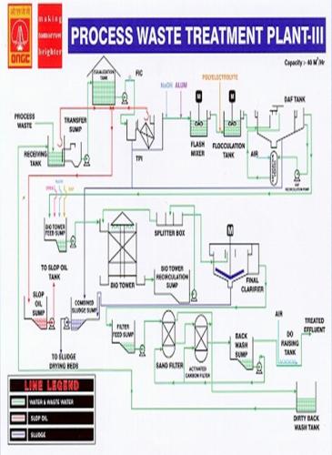
PROCESS WASTE WATER TREATMENT PLANT: PHASE – III
DESIGN CRITERIA
INFLUENT CHARACTERISTICS:
Sl.N | PARAMETER | VALUES | POLUTANT LOAD ( Kg/day) | GPCB Limits |
1. | pH | 5.5 -9.0 | 6.5 -8.5 | |
2. | Flow ( m3/hr) | 40 | 960 | |
3. | BOD | 50-150 (mg/l) | 48 -144 | 15 (mg/l) |
4. | Oil and Grease | 5 -150 (mg/l) | 4.8 -144 | 10(mg/l) |
5. | Free oil | 5 -90 (mg/l) | ||
6. | Emulsified oil | 5 – 60 ( mg/l) | ||
7. | Sulphides | 5 -10 (mg/l) | 4.8 -9.6 | 0.5(mg/l) |
8. | Suspended solids | 50 -250 (mg/l) | 48 -240 | 20(mg/l) |
9. | COD | 500 -2000 (mg/l) | 480 - 1920 | 50(mg/l) |
10. | Temp | Ambient | ||
11. | Dissolved oxygen | 5.0(mg/l) (Min) | ||
12 | Phenols | 1 (mg/l) |
TREATMENT PHILOSOPHY
The combined process waste generated from the expansion Units (Phases-III /IIIA) is received as a single stream under pressure into the proposed receiving tank which is the first unit of process waste treatment plant.
The process effluent stream contains pollutants like oil & grease, both free and emulsified, BOD, COD, Sulphides, Phenols and suspended solids which are required to be removed so as to meet the Gujarat Pollution Control Board Standards.
Thus, this stream will have to undergo physico-chemical treatment comprising of TPI and DAF for removal of free and emulsified oil and grease, suspended solids, biological treatment comprising of plastic media bio-tower for removal of BOD and part of COD.A tertiary treatment is also provided which comprises of Pressure sand filters and Activated carbon filters to achieve the desired quality of treated effluent, particularly with respect to COD and diffused aeration system to achieve desired level of dissolved oxygen.
TREATMENT SCHEME
The proposed treatment scheme includes number of unit processes for stage wise removal of various pollutants such as:
Removal of free oil in a gravity separation system comprising of Tilted plate Interceptor (TPI).
Removal of emulsified oil, suspended and colloidal particles and part of BOD and COD in a chemical treatment section incorporating dissolved air floatation system comprising of flash mixer, flocculation tank & DAF floatation tank.
Removal of dissolved organic matter contributing to BOD and COD in a biological treatment system comprising of a plastic media biotower.
The tertiary treatment section is envisaged to remove suspended solids and trace hydrocarbons from the secondary stage treated waste water viz. biological treatment section. The system comprises of pressure sand filtration for the removal of suspended solids followed by activated carbon treatment for the removal of emulsified hydrocarbons and COD. These units act as final polishing units.
Diffused aeration system is also provided to increase D.O level of treated effluent to meet Gujarat State Pollution Control Board Standards.
PRIMARY TREATMENT: for removal of free oil
The effluent treatment stream contains considerable amount of free oil. The removal of free oil is essential to meet the standards and therefore it has been considered appropriate to remove it from the waste water in the first step. The removal of hydrocarbons will eliminate toxicity effect to the micro-organism and also improve oxygen transfer efficiency in the biological system. Additionally, separation of free oil will reduce the requirement of chemicals in the chemical treatment facility.
REMOVAL OF EMULSIFIED OIL
Dissolved air floatation technology incorporating flash mixer, flocculation tank and floatation tank is provided. The emulsified hydrocarbons will be separated from the waste water by destabilizing the oil emulsion which is achieved by adding chemicals like Alum and polyelectrolyte. The chemical treatment of waste water will not only remove the emulsified hydrocarbons but shall also remove part of BOD, COD and suspended solids.
BIOLOGICAL TREATMENT
Biological treatment is provided to handle dissolved organic matter contributing to BOD and COD including compounds like sulphides & phenols. The plastic media biotower is provided as part of biological treatment in this unit. It is expected to reduce BOD by about 80%. Recirculation sump is also provided to recycle ex-biotower effluent to the inlet chamber of Biotower to maintain hydraulic loading on the tower packing which will also help in diluting the concentration of toxic constituents, if discharged in excess.
POLISHING TREATMENT:
This facility is provided to reduce the S.S and COD level of the finally treated effluent from the biological treatment. This section incorporates pressure sand filters which are followed by an activated carbon filters. These are provided in duplicate which always provides one hundred percent standby capacity.
To meet the dissolved oxygen level as per the requirements viz 5.0 mg/l in the treated effluent, a D.O dissolving tank is provided where required air is supplied through an aeration grid. Compressed air from compressor will be used for this purpose. Treated effluent from this tank will be taken to existing guard pond for final disposal.
COLLECTION OF OIL AND SLUDGES
The free oil from the ‘tilted plated interceptors’ and also from receiving tank will be collected in a slop oil sump and from the sump it will be pumped to existing slop oil pumping header.
Oily sludge from TPI units and that from DAF units will be collected in combined sludge sump. Biological sludge from clarifier will also be taken to combined sludge sump. From sludge sump it will be pumped to the existing sludge thickener for further processing in existing process waste water treatment plant.
PROCESS DESCRIPTION AND PROCESS CHEMISTRY
The combined process waste is received under pressure in the receiving tank (105-T-01). A provision is made to separate the oil to the extent possible by providing deoiler pipe. The separated free oil shall be removed through a deoiler pipe into adjacent slop oil sump (105-S-06). The effluent from receiving tank (105-T-02) is routed through a siphon in to outlet control chamber. The level in the receiving tank is maintained by the weir of outlet control chamber. This will ensure constant level in the receiving tank. From control chamber it will overflow to the transfer sump (105-S-01) and subsequently it is pumped by transfer pumps (105-P-01 A/B) to the tilted plate interceptors (105-CPI- 01 C/D). The free oil will be removed by gravity in the TPI units which will be collected through a de-oiler pipe and routed to the slop oil sump (105-S-06). The slop oil from slop oil sump shall be pumped by slop oil pumps (105-P-06-A/B). The delivery head of the slop oil pumps shall be connected to the delivery of the existing slop oil pumps (100-P-08 A/B) which lead to the existing slop oil tank. The unit will also remove the settleable solids from the effluent. The effluent from the TPI units shall flow to the flash mixer (105-R-01C). Required quantity of Alum is added in the flash mixer for breaking of the emulsion. A provision is also made to dose alkali in flash mixer if required. From flash mixer the waste water flows to the flocculation tank (105-F-01C) where polyelectrolyte solution is mixed to form bigger size flocs.
The recirculation pumps are provided to recirculate part of the clarified effluent from DAF unit. The recycle flow is used for dissolving required quantity of air in a saturation vessel. The recycle stream is pressurized at a pressure of 5.0 Kg/cm2 g and admitted in the saturation vessel. The plant air is also introduced through the bottom of this vessel at a control rate. The pressurized recycle stream is introduced to the floatation basin alongwith the flocculated effluent stream. The pressure of the stream is reduced to atmosphere in the floatation tank. As a result of this, fine air bubbles get released in the water and get entrapped in already formed flocs. This increases the size of the floc and it rises at a faster rate to the surface of the tank. These are then skimmed off by a skimmer provided for the purpose of skimming the floating layer comprising of suspended solids and hydrocarbons.
The effluent from DAF unit is collected in biotower feed sump (105-S-02). From the sump, the effluent is pumped to the inlet chamber of plastic media Biotower (105-BT-01).
The influent flow to the biotower is 40 m3/hr and recycle flow of 40 m3/hr. Thus 100% recirculation is provided to give enough hydraulic loading to the total plastic media in the biotower. The recirculation flow is maintained by Biotower recycle pumps (105-P-03A/B). The biotower essentially is filled up with random plastic media packings having approx.95% voidage and surface area 100 m2/m3 (Min). In this unit, the BOD/COD is expected to get reduced by about 80% of the influent load. Natural draft ventilation is provided for the tower. The effluent from the biotower is collected in the recirculation sump (105-S-02). From this sump the effluent is pumped by recirculation pumps (105-P-02 A/B) to the splitter box (105-SB-01). Flow in the splitter box is distributed in such a way that 40 m3/hr flow overflows to the inlet chamber of biotower while balance flow of 40 m3/hr is taken to the final clarifier (105-CL-02). The settled biological sludge from the final clarifier will be collected in the combined sludge sump. The clarified effluent from final clarifier is taken to the filter feed sump from where it is pumped by the filter feed pumps (105-P- 05 A/B) to the pressure sand filter (105-F-01 E/F).
The pressure sand filters (105-F-01 A/B) and granular activated carbon filters (105-CF-01 A/B) are employed in series. The pressure sand filter is a vertical vessel packed with sand having sizes (0.55 mm) supported on a gravel bed of 3 – 12 mm size. Out of two nos. of filters one will act as standby unit.
When the bed of one filter gets clogged with the impurities and head loss reaches maximum, it is backwashed with water and air. The SS content of the influent through this unit will get reduced from 50 mg/l to 20 mg/l. During the backwashing operation the standby unit will be put in operation. The filtered effluent from the sand filter is routed to the activated carbon filter (105-CF-01 E/F), where impurities like dissolved hydrocarbons, colour, odour, COD etc. is adsorbed on the carbon surface. It is also an essentially a vertical vessel packed with granular activated carbon. There are two Nos. of activated carbon filters (one working + one standby).
The treated effluent from ACF will be taken to backwash sump (105-T-07). From backwash sump it will overflow into D.O raising tank (105-T-08). A D.O raising tank (105-T-08) is provided to meet the dissolved oxygen requirement of 5 mg/l. The RCC tank is provided with aeration grid where compressed air is used to aerate the effluent.
After raising the D.O level the effluent is discharged into existing guard pond for final disposal.
A common air scouring and backwash system is provided for PSF and ACF. Backwash pumps (105-P-07 A/B) having capacity 100 m3/hr are provided.
A compressor unit (1+1) is provided which will supply air required for the DAF system and also for air scouring the filters and supplying air to D.O raising tank.
The oily sludge from TPI units (105-CPI-01C/D) and DAF units (105-DAF-01C/D) will be collected in the combined sludge sump (105-S-05). The sludge sump shall also receive bio-sludge from final clarifier. From the combined sludge sump, it shall be pumped by screw pumps (105-P-05 A/B) to the existing sludge thickener.
The chemical solution preparation and dosing facilities are provided in a chemical house. For each chemical two numbers of tanks are provided each having capacity of 12 hours. These tanks are located on the ground floor of the chemical house. All chemical solutions are dosed by dosing pumps (metering type) provided for the purpose. All dosing pumps are provided on the basis of 100% standby provision.
PROCESS CHEMISTRY
CHEMICAL COAGULATION:
Alum is used as coagulant for precipitating the suspended solids. When alum is added to waste water, the reaction that takes place is as follows:
Al2 (SO4)314 H 2O + 3 Ca (HCO3)2 à 3Ca SO4 + 2 Al(OH) 3 +
6CO2 + 14 H 2O
This reaction results in reduction of pH of the wastewater. The Aluminium hydroxide is in the form of a gelatinous floc that settles slowly through the waste water or floats on the surface with fine air bubble. Alum and polyelectrolyte are also dosed to destabilize the oil emulsions and producing other changes.
BIOLOGICAL TREATMENT:
Micro-organisms play a very vital role in the biological degradation of
the organic matter present in the waste. Bacteria, fungi, algae, protozoa, rotifers, crustaceans and sometimes viruses actively participate in the biological transformation of the organic matter and the end products of the biological degradation are the formation of fresh microbial cells and carbondioxide etc. During this process the organic substances present in the waste, both in the dissolved and suspended and colloidal state are metabolized in presence of air. The biochemical oxygen demand (BOD) of the waste is reduced. Temperature and pH play a vital role in the metabolic activity. Metabolic activity increases with temperature, doubling with every ten degrees centigrade rise in temperature upto a certain limit. The micro-organisms use the carbon, nitrogen, phosphorous and other trace elements, present in the waste, for the synthesis of fresh cells. Most of the industrial waste waters are deficient in the nutrients such as nitrogen phosphorous with the exception of the waste water from food and fermentation group of industries. The waste waters from petroleum and petrochemical industries are deficient in nitrogen and phosphorous. These wastes are rendered amenable for biological treatment by suitable adaptation of the micro-organisms to the organic constituents present in the waste. A culture which is very rich in microbes, which are most active on oils will be developed under field conditions from normal solids which are contaminated with oil.
PHENOL REMOVAL:
The microbial culture developed will also be suitably acclimatized to degrade phenol.
Phenol + O2 (from air) + microbes à New microbial cells + CO2
+ water
PRODUCTS OF THE TREATMENT FACILITY
SLOP OIL FROM RECEIVING TANK (105-T-01) AND TPI UNITS (105-CPI-01 C/D)
Flow: = 40 m3/hr
Total oil at inlet mg/l: = 50-150 mg/l
Free oil (mg/l): = 90 mg/l
Emulsified oil: = 60 mg/l
Free oil at outlet: = 10 mg/l
Therefore, Free oil removed: = 90-10 = 80 mg/l
Quantity of free oil removed: 40 x 24 x 80 x 1000
106
= 76.8 Kg/day
With 10% concentration
Volume of slop oil = 76.8 x 100
10 x 1000
= 0.77 m3/day
SLUDGE PRODUCTION:
Oily sludge from TPI unit:
Flow: = 40 m3/hr
T.S.S. at inlet: = 50 -250 mg/l
Considering S.S in outlet: = 125 mg/l
S.S.removed: 250 – 125 = 125 mg/l
Quantity of S.S in underflow: 40 x 24 x 125 x 1000
106
= 120 Kg/day
With 1.5% concentration
Volume of oily sludge
From TPI( Max) = 120 x 100
1.5 x 1000
= 8 m3/day
SLUDGE FROM DAF UNIT:
Flow: = 40 m3/hr
Total oil at inlet: = Emulsified oil + Free oil
= 60 +10 = 70 mg/l
Outlet: 10 mg/l
Therefore, oil removed in DAF unit: 70 – 60 = 60 mg/l
Quantity of oil removed: 40 x 24 x 60 x 103
106
Scum due to oil: = 57.6 Kg/day
ALUM SLUDGE FROM DAF UNIT:
Alum dose: = 30 ppm
1 Kg mole of Alum (Al2 (SO4)314 H 2O) will produce 2 Kg mole of Aluminium hydroxide (Al(OH) 3) viz. 594 ppm will produce 156 ppm of Al(OH) 3
Therefore, Alum sludge produced due to aluminium hydroxide when 1 ppm of Alum is dosed: = 156/594 = 0.26 ppm
50 ppm Alum dose (Max) will produce: 0.26 x 50 = 13 ppm
Sludge produced in DAF unit : = 40 x 24 x 13 x 1000 106
= 12.48 Kg/day (say 12.5 )
SLUDGE DUE TO SUSPENDED SOLIDS:
Flow: = 40 m3/hr
T.S.S at inlet: = 125 mg/l
T.S.S at outlet: = 50 mg/l
Therefore, T.S.S removed in the unit: 125 – 50 = 75 mg/l
Quantity of S.S removed: 40 x 24 x 75 x 1000
106
= 72 Kg/day
TOTAL SLUDGE = 57.6 +12.5 + 72 = 142.5 Kg/day
With 5% consistency in Scum vol of sludge:
= 142.5 x 100
5 x 1000
= 2.85 m3/day
Therefore, Total oily & Chemical sludge: 120 + 142.5
= 262.5 Kg/day
Volume of sludge produced: 8 + 2.85 = 10.85 m3/day
= Say 11 m3/day
BIOLOGICAL SLUDGE:
Flow: = 40 m3/day
Inlet BOD: = 150 mg/l
Outlet BOD: = 15 mg/l
BOD removed in biotower: = 150 – 15 = 135 mg/l
Therefore, quantity of BOD removed:
= 40 x 24 x 135 x 1000
106
= 129.6 Kg/day
Sludge produced = 0.15 Kg/Kg BOD removed
= 0.15 x 129.6 = 19.44 Kg/day
= Say 20 Kg/day
Volume of biosludge with 1% consistency:
= 20 x 100
1 x 1000
= 2.0 m3/day
Total quantity of sludge produced =
= Oily & chemical sludge + Biological sludge
= 262.5 + 20 = 282.5 Kg/day
And Sludge volume = 11 + 2 = 13 m3/day
CHEMICAL DOSING FACILITY
ALKALI REQUIREMENT:
Flow = 40 m3/hr
Recommended Dosage = 50 mg/l
Therefore, Quantity required = 40 x 24 x 50 x 1000
106
= 48 Kg/day
This is to be dosed as and when and required.
ALKALI SOLUTION TANKS (105-T-07 A/B):
Quantity of acid required = 48 kg/day
No.of tanks = 2
Capacity of each tank = 12 Hrs
Concentration = 10%
Volume of each tank = 48 x 100 x 1
2 x 10 x 1.06
= 226.41 lts
= 226.5 ltrs
However provide tank volume of` = 1.0 m3
Size of the tank = 1.15 M dia x 1.0 M LD + 0.3 M FB
Dosing rate: = 226.5 / 12 = 18.875 LPH
Range of metering pump provided
(105 – M P – 05 ) = 0 to 200 LPH
Head = 15 m
ALUM REQUIREMENT: (Al2 (SO4)314 H 2O )
Flow = 40 m3/hr
Recommended dose of Alum = 30 – 50 ppm
Therefore, Quantity of Alum
required at max. dose = 40 x 24 x 50 x 1000
106
= 48 Kg/day
= Say 50 Kg/day
ALUM SOLUTION TANKS: (105 – T – 03 A/B):
Quantity of Alum required: = 50 Kg/day
No. of tanks: = 2
Capacity of each tank = 12 Hrs
Concentration of solution = 10%
Volume of each tank = 50 x 100
2 x 10
= 250 Litres
However provide a tank volume of: = 1.0 m3 ( As per NIT)
Therefore, size of the tank provided = 1.15M Dia x 1.0 M LD + 0.3 M FB
Dosing rate = 250/12 = 20.8 LPH
Range of metering pump
Provided (105-MP- 01 A/B) = 0 to 200 LPH
Head = 15 M
NUTRIENT REQUIREMENT:
Flow = 40 m3/hr
Inlet concentration of BOD = 150 mg/l
Therefore total BOD at the inlet of
Bio tower = 40 x 24 x 150 x 1000
106
= 144 kg/day
For biotower BOD: N : P ratio provided is 100 : 5 : 1
The nutrient requirement is calculated considering total BOD load at inlet of trickling filter.
DI–AMMONIUM PHOSPHATE REQUIREMENT :( (NH4)2HPO4)
Phosphorous required = 144 x 1
100
= 1.44 Kg/day
Therefore, Quantity of DAP required = 1.44 x 132
31
= 6.13 Kg/day ( Say 6.2 kg/day)
DI–AMMONIUM PHOSPHATE SOLUTION TANKS:(105-T-06 A/B):
Quantity of DAP required = 6.2 Kg/day
No. of tanks = 2
Capacity of each tank: = 12 Hours
Concentration of solution = 10%
Therefore Volume of each tank = 6.2 x 100
2 x 10
= 31 litres
However provide volume of tank = 1.0 m3
Therefore size of the tank = 1.15 M Dia x 1.0 M LD + 0.3 M FB
Dosing rate = 31/12 = 2.6 LPH
Range of metering pump provided (105 – M P – 04 A/B) = 0 to 200 LPH
Head = 15M
NITROGEN REQUIREMENT:
‘N’ required = 144 x 5
100
= 7.2 Kg/day
Nitrogen available in DAP = (28 / 132) x 6.2
= 1.315 Kg/day
Therefore, ‘N’ to be supplied by urea = 7.2 – 1.315 Kg/day
= 5.885 Kg/day
Therefore, Quantity of Urea required = 5.885 x ( 60 / 28)
= 12.6 Kg/day
= Say 13 Kg/day
UREA SOLUTION TANKS (105 – T – 05 A/B):
Quantity of Urea required = 13 Kg/day
No. of tank = 2
Concentration of solution = 10%
Volume of each tank = 13 x 100
2 x 10
= 65 Litres
However provide volume of tank = 1.0 m3 ( As per NIT)
Therefore, size of the tank = 1.15 M Dia x 1.0 M LD + 0.3 M FB
Dosing rate = 65 / 12 = 5.42 LPH
Range of metering pump provided
(105 – MP – 03 A/B) = 0 – 200 LPH
Head = 15 M
POLYELECTROLYTE REQUIREMENT:
Flow = 40 m3/hr
Recommended dose of polyelectrolyte = 1 – 1.5 ppm
Therefore, Quantity of polyelectrolyte
required at max. dose = 40 x 24 x 1.5 x 1000
106
= 1.44 Kg/day ( Say 1.5 Kg/day)
DEOILING POLYELECTROLYTE SOLUTION TANKS (105–T–04 A/B):
Quantity of polyelectrolyte required = 1.5 Kg/day
No. of tanks = 2
Concentration of solution = 0.5 %
Volume of each tank = 1.5 x 100
2 x 0.5
= 150 Litres
However provide volume of tank = 400 litres ( As per NIT)
Therefore, size of the tank = 0.8 M Dia x 0.8 M LD + 0.3 M FB
Dosing rate = 150 / 12 = 12.5 LPH
Range of metering pump provided
(105 – MP – 03 A/B) = 0 – 200 LPH
Head = 15 M
Sl.N | Chemicals/ Nutrient | Consumption Kg/day | Quantity for 1 Month ( MT/month) |
1. | Alum | 50 | 1.5 |
2 | Polyelectrolyte | 1.5 | 0.045 |
3 | Urea | 13 | 0.4 |
4 | DAP | 6.2 | 0.186 |
5 | Alkali* | 48 | 1.44 |
* In the present running condition Alkali is not dosed as pH correction is not required because of the incoming influent pH is within the design range for treatment
OPERATION PROCEDURE
RECEIVING TANK, (105-T-01); TRANSFER SUMP (105-S-01) AND PUMPS (P-01-A/B):
OBJECTIVE:
This unit is provided to collect the combined waste water from process units, and pump it to TPI unit for free oil removal.
UNIT DESCRIPTION:
Receiving tank and transfer sump are rectangular in shape and constructed in RCC. The transfer sump is attached to receiving tank (105-T-01) and transfer pumps (P-01 A/B) are installed at grade. The receiving tank is covered with GI cover. Level indicator of float and pulley type is also provided in the receiving tank.
PROCEDURE FOR NORMAL OPERATION:
Allow the effluent to be collected in the receiving tank. From the tank, the effluent goes to the transfer sump. An adjusted weir arrangement is provided.
When the water level reaches near to its normal working level start one of the effluent transfer pump.
High and low level switches are provided in the sump for starting the pump automatically at high level and tripping the pump at low level. However the pump can also be started/ stopped manually.
Keep the delivery valve open for the pumps to be operated on auto mode.
FOR PUMP OPERATION PLEASE SEE END PAGES.
TPI UNITS: ( 105 – CPI – 01 C/D)
OBJECTIVE:
This unit is provided to remove free oil from the effluent to make it suitable for physico-chemical treatment in the DAF unit.
UNIT DESCRIPTION:
TPI unit is constructed in MS. One unit is working and one unit is standby. (But, as the present Influent load is high, almost all the time both the tracks are in line.). Each unit is consisting of 2 Nos of plate packs. The effluent from the transfer sump will be pumped to the inlet of TPI unit by means of transfer pumps (105-P-01A/B).
The waste water will enter into the unit through inlet pipe. In the plate pack the oil droplets are intercepted and coalesce into larger droplets. They leave the plate pack rapidly in a counter current direction and then move upward to the surface. The free oil will be skimmed off and taken to the slop oil sump (105-S-06). Any heavy solids will settle through the plate pack and will get collected at the bottom of TPI unit. The treated effluent will flow through outlet weir into the outlet chamber.
FLASH MIXER:
OBJECTIVE:
This unit is provided to mix alum solution thoroughly with the effluent for breaking of emulsion. A provision is also made to dose alkali in flash mixer if required.
UNIT DESCRIPTION:
The unit is square in shape and constructed in RCC. The overflow from the tank is taken to the inlet of flocculation tank-I (105-F-01-A/B).
START-UP PROCEDURE:
Clean the tank, inlet chamber and opening for any obstructions / constructions debris etc.
Check mixer is working satisfactorily.
Check oil level in gear box.
NORMAL OPERATION:
Allow the waste water from TPI units (105-CPI-01 C/D) to flash mixing tank (105-R-01C).
Allow the tank to fill upto the normal operating water level.
Add the required quantity of alum solution by starting the alum solution dosing pumps.
Keep the mixer ‘ON’ while adding alum solution in the effluent.
Allow the chemically treated effluent to the flocculation tanks(105-F-01)
SHUT-DOWN PROCEDURE:
Stop the effluent to the unit from (105-CPI-01 C/D) by stopping the transfer pumps.
Stop solution dosing by switching “OFF” the solution dosing pumps.
Stop flash mixer of the unit, if required.
FOR PUMP OPERATION PLEASE SEE END PAGES.
FLOCCULATION TANKS (105-F-01 A/B):
OBJECTIVE:
This unit is provided to flocculate the flocs formed in the flash mixing tank. Polyelectrolyte is added in the flocculation tank to aid the flocculation process and to build the bigger flocs in the flocculation tank-I.
UNIT DESCRIPTION:
The units are square in shape and constructed in RCC with epoxy lining from inside. The tank is provided with paddle agitator for proper mixing. The overflow of the flocculation tanks (105-F-A/B) is over flowing into the outlet chamber from where the flocculated effluent is conveyed to the DAF tank (105-DAF-01C/D).
START-UP PROCEDURE:
Clean the tank, inlet chamber and opening for any obstructions/debris etc.
Check that agitator is in working condition.
Check oil level in gear box unit.
NORMAL OPERATION:
Allow the effluent into the tank.
Allow the tank to fill upto the normal operating water level.
Add the required quantity of deoiling polyelectrolyte solution by starting the respective deoiling polyelectrolyte solution dosing pumps.
Keep the agitator ‘ON’ while adding deoiling polyelectrolyte solution in the tank.
The flocculated effluent will overflow into the outlet chamber and subsequently it shall be taken to the DAF tank (105-DAF-01 C/D).
SHUT-DOWN PROCEDURE:
Effluent to the flocculation tank to be isolated.
Stop adding deoiling polyelectrolyte by switching off the respective dosing pumps. Switch off the agitator motor if required.
Stop agitator of the flocculation tank by pressing the button ‘OFF’ if required.
DISSOLVED AIR FLOTATION UNIT (105 – DAF – 01C/D) & RECYCLE PUMPS ( 105-P-08 A/B):
OBJECTIVE:
This unit is provided to remove emulsified oil and suspended solids from the effluent. Flocs formed in a flocculation tank will also be removed in the unit by dissolved air flotation process.
PRINCIPLE OF AIR FLOATATION:
Following three components are involved in the dissolved air flotation system:
1. Flotation basin (105-DAF-01 C/D)
2. Saturation Vessel (105-V-01 A/B)
3. DAF recycle pumps (105-P-08 A/B/C)
Flotation is a unit operation used to separate solid (particulate matter) or liquid particles from liquid phase. Separation is brought about by introducing fine air bubbles into the liquid phase. The bubbles attach to the particulate matter and the buoyant force of the combined particle and air bubbles is great enough to cause the particles to rise to the surface. Particles that have a higher density than the liquid can thus be made to rise. The rising of particles with lower density than the liquid can also be facilitated i.e emulsified oil globules etc.
PROCESS:
The Dissolved air flotation unit comprises of Flocculation tank, Floatation Basin, Saturation vessel & recycle pump. One unit is in working condition & one is in standby mode. (At present, due to high Influent load both the tracks are being in line). Effluent from Flocculator will go to flotation basin by gravity. A part of the treated effluent from DAF tank is pumped to the saturation vessel by means of recycle pumps under pressure of about 5.0 Kg/cm2 (g). Air at a constant rate is introduced into the saturation vessel to make the effluent saturated with air. The saturated recycle flow is returned to the DAF tank flotator. When the saturated water is released under atmospheric pressure in DAF tank it forms small bubbles of air and being lighter, it carries the impurities like suspended solids, emulsified oil particles and flocs formed to the top liquid surface of the unit. The scum thus formed at the surface of the DAF tank is skimmed and routed to combined sludge sump. The suspended solids sludge is also routed to sludge sump.
UNIT DESCRIPTION:
The DAF Floatation tank is circular in shape and constructed in RCC having epoxy lining on internal surface. Inlet of the flocculated effluent is through MSEP pipe in the feed well of the DAF tank provided at the centre of the unit. Outlet of the treated effluent is through adjustable HDPE weirs provided in the peripheral launder to collect the effluent and guide upto the outlet chamber. Bottom of the unit is provided with a slope of 1 in 12. The sludge scrapping mechanism and scum skimming arms provided in the tank. The sludge can be drawn off through sludge pipe provided at the bottom of the unit. The scum can be skimmed off and collected in the scum box. Floatation tank is provided full dia fixed bridge with MS stairs and hand railing.
START-UP PROCEDURE:
Check the mark on the oil gauge, condensate drain should be opened at regular intervals to drain possible condensation. The oil filling plugs have a vent hole. Make sure this hole is not closed by paint and is open at all the time. Check mark on the oil gauge to make sure that oil is maintained at proper level. The oil level shows that the gears are partly submerged. Lubrication of full contact surface of the teeth depends on the pumping action created by the meshing of the teeth of the pinion and main gear.
Oil to be used is Enklo 40 or equivalent and must be removed after every six months or so.
Check that clearance between squeezers and the tank bottom should be in the range of 6 to 12 mm at any point. Minor adjustment in the clearance can be made in the squeezers. For a major adjustment, the adjustment bolts provided on the centre cage at its junction with rake arm is tightened or loosened.
Keep proper tension on variable speed chain. Rotate entire mechanism to check for free movement. More than one person may be required for its rotation.
Push motor buttons ‘On’ and allow them to rotate. Dry check for overheating of motors, gears and bearings. Check the direction of rotation. It should be clockwise when viewed from top.
Normal Operation:
Regularly check the oil level in gear box and fill up if required.
Operate the DAF mechanism; this will help in scrapping the oily and chemical sludge towards the sludge pit.
Overheating of motors, gears and bearings shall be checked at regular intervals.
Watch for any loose mechanical parts and misalignment or any unusual noise in the system.
Check wearing parts periodically and examine if any excess wearing is taking place.
Fill bearing grease cup if necessary.
Open sludge valve to remove the sludge as per the requirement. It is preferable to keep the sludge valve crack opened and have continuous sludge bleeding.
LP steam heating is provided near scum box for heating the oily froth if required.
Shut-down Operation:
In case of power failure the rack arm assembly driven by electric motor will stop.
Press the drive motor button ‘STOP’.
Immediately inform operator to stop effluent.
BIOTOWER FEED SUMP & PUMPS (105-S-02 & 105-P-02 A/B):
OBJECTIVE:
This unit is provided to collect the effluent from DAF unit and to pump it to Biotower for removing BOD/COD from the waste water.
UNIT DESCRIPTION:
The sump is rectangular in shape and constructed in RCC. Horizontal centrifugal pumps are provided to transfer effluent to Biotower. High and low level switches are provided for alarm and pump control. The dosing facility to dose urea and DAP as nutrient is provided in the sump. Also provision is made to dose alkali in this sump.
START-UP PROCEDURE:
Clean the sump as well as all incoming pipes.
Check all the valves are operating smoothly and are installed in correct position.
Check all pumps are properly installed in respective position.
Check rotation of pumps and check for any abnormal noise, vibration and overheating etc.
High and low level switches are provided in the sump for starting the pump automatically at high level and tripping the pumps at low level. However operate the pumps manually. In auto mode only one pump will be in operation and
Check oil level in the pumps.
Check all instruments are working properly.
NORMAL OPERATION:
Effluent from DAF units (105-DAF-01 C/D) is received in the Biotower feed sump.
Start one of the Biotower feed pumps to pump effluent to Biotower to transfer effluent to inlet of biotower. These pumps operate on auto start/stop.
Add the required quantity of urea and DAP in the biotower feed sump, by starting the respective dosing pumps.
BIOTOWER (105-BT-01):
OBJECTIVE:
This unit is provided to remove part of organic load due to BOD, phenols, ammonical nitrogen and sulphides from the combined effluent. It will also help in reducing the shock load intensity due to slug load of hydrocarbons.
PROCESS:
When the combined effluent is allowed to percolate through plastic media, it flows in the form of a thin layer and a biological slime consisting of facultative bacteria adsorbs and absorbs the organic matter as food. The spraying action through distribution arm and ventilation provided on peripheral wall of biotower keeps the slime layer in completely aerobic conditions. When the slime layer becomes thick, inner surface becomes anaerobic and the slime layer gets sloughed from the media surface. New layer is formed again. This is more or less continuous process. For high rate operation the waste water is recirculated through biotower recirculation sump and pumps. The unit also can be operated without recycle flow.
Unit description
The unit is circular in shape and packed with plastic media having surface area over 100 M2/M3. The unit is provided with an inlet chamber to feed the effluent to the rotating arms of biotower through central feed column. 4 Nos. rotating arms of biotower are connected with central feed well. The distributed arms are rotated under the hydrostatic head. Thus the effluent is continuously distributed on the filter media. Openings are provided at the bottom of the peripheral wall for natural draft ventilation to keep the biological activity in the biotower in fully aerobic condition. The unit consists of peripheral launder for collection of filterate, under drains, media, central feed column and rotating distribution arm etc. The unit is provided with RCC staircase to approach the top of the unit.
Start-up Operation
Check the filter media top for uniformly and any projected media or obstructions to distribution arm.
Check all the nozzles of distribution arm for any chocking etc.
Check tension of tie rods and levels of all distribution arms.
Ensure free movement of distribution arm by moving it manually.
Check inlet chamber for any debris or foreign material.
Check lubrication of bearings etc.
If all above is ok the unit is ready for taking process waste.
NORMAL OPERATION:
The distribution arm should rotate by hydrostatic pressure available.
Operate the biotower feed pump and allow effluent to flow to the inlet chamber of biotower.
Check rotation of distribution arm and uniform distribution of waste water over filter media.
Check the clogged spray nozzles by stopping arm if required.
Operate one of the biotower recycle pump to recirculate the effluent back to the inlet chamber of biotower.
Higher recirculation with less organic load will result in washing of bacterial film from the surface of the media.
Operation problems:
Ponding:
Ponding in the surface is sometimes observed. This may be due to excessive growth of organic material and possible chockage of filtermedia. In such case rake the top layer of the media upto the depth of 20 to 30 cm and wash the filter media with jet of water.
Odours:
When raw effluent becomes septic and sprayed on filter media it gives rise to odours. This can be controlled by eliminating stagnation in previous units.
Fly Nuisance:
Sometimes filter files ‘psychoda’ infest the filter and cause nuisance. In such cases chlorinate the waste water or supply pesticide on surface once in a week to kill the larvae.
NOTE; 1. Biotower is provided with adequate no. of sight glasses to facilitate the viewing of the condition of the biofilm.
BIO-TOWER RECYCLE SUMP & PUMPS (105-S-03 & 105-P-03 A/B)
OBJECTIVE:
This unit is provided to collect the effluent from the biotower and pump it to the inlet chamber of biotower.
UNIT DESCRIPTION:
The bio-tower recycle sump is rectangular in shape and constructed in R.C.C. Two Nos. of vertical centrifugal pumps are provided in the sump. High and low level switches for alarm and pump control are also provided in the sump to control the start/stop of the pumps. The effluent from the Biotower is collected into the biotower recycle sump. Platform with hand railing is also provided to support the level switches as well as operation & maintenance purpose.
START-UP PROCEDURE:
Clean the sump and incoming pipe and outgoing pipe.
Check all valves are operating smoothly and installed in correct position.
Check all pumps are properly installed in respective position.
Check rotation of pump and observe for any abnormal noise, vibration, and overheating.
Check oil level in the pumps.
Check and ensure all instruments are functioning properly.
NORMAL OPERATION:
Allow effluent to overflow from Biotower into the sump.
Start one or two pumps as per requirement and slowly open the discharge valve to transfer the effluent to inlet chamber of biotower.
High and low level switches are provided in the sump for starting the pump automatically at high level and tripping the pumps at low level. However can also be operated manually.
Keep the delivery valve open for the pumps to be operated in auto mode.
SPLITTER BOX:
OBJECTIVE:
This unit is provided to split the effluent to the biotower and to clarifier, in equal quantity.
UNIT DESCRIPTION:
The splitter box is provided to split the effluent as per the recycle requirement to biotower and to final clarifier.
This unit is constructed in RCC adjacent to Biotower above ground. The effluent is collected in the recycle sump and pumped to the splitter box through biotower recirculation pumps (105-P-03 A/B).It is provided to divide effluent in equal quantity & one ‘Q’ is taken to biotower inlet chamber of biotower & one ‘Q’ is taken to clarifier. The splitter box comprises of the following:
Central chamber
Outlet chamber to feed effluent to biotower.
Outlet chamber to take effluent to final clarifier.
The box is provided with rectangular weirs on both sides, so that equal quantities of effluent can be fed to biotower and to final clarifier. It is also possible to adjust the flows as required, to both the units by adjusting the gate operation. Central chamber of the splitter box is provided with a platform & hand railing for the operation of gates etc.
START-UP PROCEDURE:
See that the splitter box is free from debris etc.
Ensure that the gate is installed at proper location.
Check that rectangular weirs are leveled properly.
Check that gates /valves are operating smoothly.
NORMAL OPERATION:
Pump the effluent to the central chamber of the splitter box.
Allow the effluent to overflow to the outlet chambers through respective weirs.
Check the flow at respective weir.
Normal recirculation rate of effluent is 100% of the incoming effluent.
In case of diverting total effluent to biotower, close the outlet valve leading to final clarifier & open the gate leading effluent to biotower.
FINAL CLARIFIER:
OBJECTIVE:
This unit is provided for the purpose of separating the solids from the treated effluent from the biotower. The underflow of the clarifier is collected in the combined sludge transfer sump & pumped to existing sludge lagoon. The overflow from clarifier which is treated effluent in the dry weather filter feed sump (105-S-04).
UNIT DESCRIPTION:
The clarifier unit is circular in shape and constructed in RCC. The effluent enters the feed well from top. The effluent is allowed to flow slowly and continuously through the feed well from centre to circumference radially. Sedimentation of biological slime takes place and clear effluent is collected in peripheral launder. Scrapper is moved by centrally driven mechanism and is provided with neoprene squeezes. It scrapes the sludge continuously towards sludge collection pit. The unit is provided with full dia. fixed bridge with access stairs and handrailing for Inspection/Operation/Maintenance purpose.
Check the mark on the oil gauge, condensate drain should be opened at regular intervals to drain possible condensation. The oil filling plugs have a vent hole. Make sure this hole is not closed by paint and is open at all the time. Check mark on the oil gauge to make sure that oil is maintained at proper level. The oil level shows that the gears are partly submerged. Lubrication of full contact surface of the teeth depends on the pumping action created by the meshing of the teeth of the pinion and main gear.
Oil to be used is servomesh 40 or equivalent and must be removed after every six months or so.
Check that clearance between squeezers and the tank bottom should be in the range of 6 to 12 mm at any point. Minor adjustment in the clearance can be made in the squeezers. For a major adjustment, the adjustment bolts provided on the centre cage at its junction with rake arm is tightened or loosened.
Keep proper tension on variable speed chain. Rotate entire mechanism to check for free movement. More than one person may be required for its rotation.
Push motor buttons ‘On’ and allow them to rotate. Dry check for overheating of motors, gears and bearings. Check the direction of rotation. It should be clockwise when viewed from top.
NORMAL OPERATION:
During normal operations remove the sludge atleast two to three times during the shift. It is preferable to keep sludge valve crack open and have continuous sludge bleeding.
Have a regular watch on the oil level and re-gearing etc. Check occasionally for over heating and unusual noise and loss of misaligned parts.
Observe that grease cups are always full.
Overheating of motors, gears and bearings shall be checked at regular intervals.
FILTER FEED SUMP (105-S-04) & PUMPS (105-P-04 A/B):
OBJECTIVE:
This sump is provided to collect overflow from clarifier and then pumped through pressure sand filter for removal of suspended solids.
DESCRIPTION OF UNIT:
The sump is rectangular in shape constructed in RCC above ground. Horizontal centrifugal pumps are provided to feed filters.
START-UP PROCEDURE:
Clean the sump and incoming pipes.
Check all valves are operating smoothly and installed in correct position.
Check all pumps are properly installed in respective position.
Check rotation of pump and observe for any abnormal noise, vibration, and overheating.
Check oil level in the pumps.
Check and ensure all instruments are functioning properly.
NORMAL OPERATION:
Effluent from final clarifier is collected in the sump.
Start one of the feed pumps to pump the effluent to pressure sand filters. These pumps operate on Auto start/stop.
High and low level switches are provided in the pumps for starting the pump automatically at high level and tripping the pump at low level. However operate the pumps manually.
PRESSURE SAND FILTER: (105-F-01 A/B):
OBJECTIVE:
This unit is provided to remove suspended solids from treated effluent.
DESCRIPTION OF UNIT:
The effluent enters from top and comes out from bottom. Arrangement for air scouring and backwashing with treated water is provided. Flow indicators are provided for measuring feed flow, backwash flow and air flow. For air scouring compressed air is to be used. Pressure reducing valve is provided to reduce the compressed air pressure. Backwashing of filters will be required to be carried out when pressure drop across a filter increases more than 0.8 kg/cm2 g or once in 24 hours.
START-UP PROCEDURE:
Check all the valves for smooth operation.
Check that all instruments are functioning properly.
Make sure that bed support media gravel and filter media sand is properly filled to required level.
First backwash the filters as per backwashing procedure before taking the filters into operation.
Start one of the filter’s feed pumps 105-P-04 A/B and slowly open the inlet valve of the filter to be taken into operation. By doing so air inside the filter will get replaced with effluent.
When complete air has been replaced by effluent slowly open the outlet valve of the filter.
Check for any leakage from the filter nozzle, piping, valves etc.
Close vent valve when complete air is vented.
Thus the filter is in operation.
SHUT-DOWN PROCEDURE:
Take the standby filter into operation or close the pumps 105-P-04 A/B as per requirement.
Close the inlet valve of the filter, and then close the outlet valve of the filter.
The filter can be drained by opening the drain valve. At the time of draining, vent valve should be kept open.
BACKWASHING:
Backwashing is required when lot of solids has got settled in the filtering sand. This gives large resistance to the flow of effluent and pressure drop across the filter increases. Filters are to be backwashed if pressure drop exceeds 0.8 kg/cm2.
Filters should be backwashed after every 24 hours.
The backwashing is to be done by treated effluent and air scouring by compressed air.
Isolate the filter to be backwashed by closing inlet and outlet valves.
Open drain valve and drain the filter.
Open air inlet valve and outlet valve for air scouring.
Admit the air to pass through the bed for about 5 minutes.
After air scouring is over, close air inlet and outlet valve.
Start one of the backwash pumps 100-P-04 A/B.
For water backwashing, open backwash inlet valve and outlet valve.
Allow the water to pass through bed for about 10 minutes.
Backwashed water will go to inlet receiving sump through drain.
Keep checking the backwash outlet for clarity.
Backwashing is to be stopped when backwashed water becomes clear.
After completing backwashing of the unit close backwash inlet and outlet valve.
Open drain valve for draining the filter.
For rinsing the bed, open effluent inlet valve and allow water for about 5 to 10 min. at 25 m3/hr flow rate.
After rinsing, close drain valve and open filtered water outlet valve to take filter into operation or close inlet valve and keep filter ready to take into operation whenever required.
Each filter is required to be backwashed, once in a day irrespective of built up of pressure differential.
ACTIVATED CARBON FILTER (105-CF-01E/F):
OBJECTIVE:
This unit is provided to remove COD from the filtered water from pressure sand filter before it is sent to FEDS.
DESCRIPTION OF UNIT:
The unit is a vertical pressure vessel, fabricated from carbon steel plates. The effluent enters from the top and comes out from the bottom. Air scouring and backwash system is same as that of pressure sand filters. Washing with L.P steam with pressure reducing valve is provided as additional facility for activated carbon filter units.
START-UP PROCEDURE:
Check all the valves for smooth operation.
Check that all instruments are functioning properly.
Make sure that bed support media gravel and filter media activated carbon is properly filled to required level.
First backwash the filters as per backwashing procedure before taking the filters into operation.
Start one of the filter’s feed pumps 105-P-04A/B and slowly open the inlet valve of the filter to be taken into operation. By doing so air inside the filter will get replaced with effluent.
When complete air has been replaced by effluent slowly open the outlet valve of the filter.
Check for any leakage from the filter nozzle, piping, valves etc.
Close vent valve when complete air is vented.
Thus the filter is in operation.
SHUT-DOWN PROCEDURE:
Take the standby filter into operation or close the pumps 105-P-04 A/B as per requirement.
Close the inlet valve of the filter, then close the outlet valve of the filter.
The filter can be drained by opening the drain valve. At the time of draining, vent valve should be kept open.
BACKWASHING:
Backwashing is required when lot of solids has got settled in the filtering media i.e activated carbon. This gives large resistance to the flow of effluent and pressure drop across the filter increases. Filters are to be backwashed if pressure drop exceeds 0.8 kg/cm2.
Filters should be backwashed after every 24 hours.
The backwashing is to be done by treated effluent and air scouring by compressor air.
Isolate the filter to be backwashed by closing inlet and outlet valves.
Open drain valve and drain the filter.
Open air inlet valve and outlet valve for air scouring.
Admit the air to pass through the bed for about 5 minutes.
After air scouring is over, close air inlet and outlet valve.
Start one of the backwash pumps 105-P-07 A/B.
For water backwashing, open backwash inlet valve and outlet valve.
Allow the water to pass through bed for about 10 minutes.
Dirty Backwash water will go to dirty backwash holding tank under pressure.
Keep checking the backwash outlet for clarity.
Backwashing is to be stopped when backwashed water becomes clear.
After completing backwashing of the unit close backwash inlet and outlet valve. Stop backwash pumps 105-P-07 A/B.
Open drain valve for draining the filter.
For rinsing the bed, open effluent inlet valve and allow water for about 5 to 10 min. at 25 m3/hr flow rate to drain.
After rinsing, close drain valve and open filtered water outlet valve to take filter into operation or close inlet valve and keep filter ready to take into operation whenever required.
Provision is made to inject steam at L.P steam into the bed to regenerate or to remove Hydrocarbon. Steam is to be injected once in 7 days.
Each filter is required to be backwashed, once in a day irrespective of built up of pressure differential.
BACKWASH WATER SUMP (105-S-07) & PUMPS (105-P-07 A/B):
OBJECTIVE:
The sump is provided to collect the treated effluent from the Activated carbon filters. The overflow from the sump goes to the D.O raising tank. The treated effluent is pumped by the horizontal centrifugal pumps to the pressure filters and activated carbon filters for backwash.
DESCRIPTION OF UNIT:
The sump is rectangular in shape and constructed in RCC. Low level switch is provided in the sump to protect the dry running of the pump.
START-UP PROCEDURE:
Clean the sump and incoming pipe and outgoing pipe.
Check all valves are operating smoothly and installed in correct position.
Check all pumps are properly installed in respective position.
Check rotation of pump and observe for any abnormal noise, vibration, and overheating.
Check oil level in the pumps.
Check and ensure all instruments are functioning properly.
NORMAL OPERATION:
Treated effluent from ACF is collected in the sump.
Start one of the backwash pumps to pump the treated effluent to pressure sand filters to ACF for backwashing.
Low level switch is provided in the sump for tripping the pumps at low level. However the pump is to be started manually.
FOR PUMP OPERATION PLEASE SEE END PAGES.
D.O RAISING TANK (105-T-08):
OBJECTIVE:
The D.O raising tank is provided to meet the dissolved oxygen levels as per the requirements viz. 5.0 mg/l in the treated effluent.
DESCRIPTION OF UNIT:
The D.O raising tank constructed in RCC. It is provided with air diffuser pipe where compressed air is used to aerate the effluent. The compressed air is provided by means of compressor.
The treated effluent from backwash sump will overflow into D.O raising tank.
After raising the D.O level of the treated effluent, it is discharged into existing guard pond for final disposal.
START-UP PROCEDURE:
Clean the tank.
Check aeration grid is installed properly.
Ensure D.O meter is functioning properly.
NORMAL OPERATION:
Allow treated effluent to overflow into the D.O raising tank from Backwash sump.
Open air valve & allow air to bubble through the effluent to raise the dissolved oxygen level.
Observe the D.O regularly.
SHUT-DOWN PROCEDURE:
Close air valve.
Stop effluent to the tank.
COMBINED SLUDGE TRANSFER SUMP (105-S-05) & PUMPS
(105-P-05 A/B):
OBJECTIVE:
The sump is provided to collect the oily sludge from TPI units (105-CPI-01 C/D) and DAF units (105-DAF-01 C/D). The sludge sump shall also receive biosludge from final clarifier (105-CL-02). From the combined sludge sump it shall be pumped by screw pumps (105-P-05 A/B) to the existing sludge lagoon.
DESCRIPTION OF UNIT:
Sump is rectangular in shape and constructed in RCC. Level switches for high and low level alarms and for pump control are provided in the sump. Single screw pumps are provided for pumping the combined sludge into the existing sludge lagoon.
START-UP PROCEDURE:
Clean the sump and incoming pipes.
Check all valves are operating smoothly and installed in correct position.
Check all pumps are properly installed in respective position.
Check rotation of pump and observe for any abnormal noise, vibration, and overheating.
Check oil level in the pumps.
Check and ensure all instruments are functioning properly.
NORMAL OPERATION:
Chemical & oily sludge from TPI & DAF / Bio sludge from clarifier is collected in the sump.
Start one of the pumps to pump the sludge
High and low level switches are provided in the pumps for starting the pump automatically at high level and tripping the pump at low level. However operate the pumps manually.
FOR PUMP OPERATION PLEASE SEE END PAGES.
SLOP OIL SUMP (105-S-06) AND PUMPS (105-P-06 A/B):
OBJECTIVE:
The sump is provided to collect the slop oil from TPI Units (105-CPI-01 C/D) and from receiving TANK (105-T-01). The slop oil from this sump is pumped to the existing slop oil tank.
DESCRIPTION OF UNIT:
The sump is rectangular in shape and constructed in RCC. Level switch for high and low level alarm and for pump control is provided in the sump. Horizontal screw pumps are provided for pumping slop oil to existing slop oil storage tank.
START-UP PROCEDURE:
Clean the sump and incoming pipes.
Check all valves are operating smoothly and installed in correct position.
Check all pumps are properly installed in respective position.
Check rotation of pump and observe for any abnormal noise, vibration, and overheating.
Check oil level in the pumps.
Check and ensure all instruments are functioning properly.
NORMAL OPERATION:
Slop oil from TPI oil separator (105-CPI-01 C/D) and from receiving tank (105-T-01) is collected in the slop oil sump.
Start one of the slop oil pumps (105-P-06 A/B) to pump slop oil to existing slop oil tank.
High and low level switches are provided in the sump for starting the pump automatically at high level and tripping the pumps at low level. However the pumps can also be operated manually.
Keep the delivery valve always open of the pumps.
FOR PUMP OPERATION PLEASE SEE END PAGES.
DIRTY BACKWASH HOLDING TANK (105-T-02):
OBJECTIVE:
The tank is provided to collect the backwash from the pressure filters and activated carbon filters. The overflow and drain are routed to the combined sludge transfer sump. Some of this backwash is recycled back to TPI units.
DESCRIPTION OF UNIT:
The tank is square in shape and constructed in RCC. Drain chambers are provided.
START-UP PROCEDURE:
Clean the tank.
Check all valves are operating smoothly and installed in correct position.
Before taking effluent check that all valves are in closed condition.
Allow the dirty backwash water from P.S.F /A.C.F into the tank.
NORMAL OPERATION:
Remove the settled solids collected in the hopper by opening the drain valve.
Allow water to the TPI unit at control flow rate. Manual outlet valve is provided.
Process the content of the tank through TPI so as to receive another backwash from the P.S.F /A.C.F.
SHUT-DOWN PROCEDURE:
Close outlet valve.
Drain the unit if required.
PUMPS OPERATION: (CENTRIFUGAL)
START-UP PROCEDURE:
a) Check that the equipment, instrument, valves and piping are secured and in proper alignment.
b) Charge bearings to the level marked, with the oil of correct grade. Do not overfill.
c) Turn unit by hand to ensure that the movement of the pump and drive shaft free.
d) Make sure that the discharge check valve is not leaking.
e) Make sure that the discharge valve is closed, the suction valve is wide open and a full supply to the suction is assured. A fully open suction valve ensures full priming.
f) Check that the priming fluid has filled up the pump casing.
g) Start the pump by pressing the adjoining start button ‘On’.
h) Note the reading on the discharge gauge. It should show normal discharge pressure for the pump.
i) Open the discharge valve gradually to full open position.
j) If every thing is O.K. the pump is now in normal operation.
NORMAL OPERATION:
a) Allow each pump to work atleast once in a shift. Watch the pressure regularly and see that the operating pressure is in normal range.
b) Log the reading of the pump discharge pressure gauge at specified intervals. Preferably at an interval of half an hour.
c) Check the bearing lubricating oil level regularly.
d) Check pumps glands and bearings for overheating, leaking etc.
e) Watch for leaks in the system and take immediate action for rectification.
f) Watch for loose mechanical parts, misalignment and any unusual noise in the system.
SHUT-DOWN PROCEDURE:
a) Close the discharge shut off valve of the pump in operation
b) Press the stop button of the pump and allow it to come to a standstill.
c) Leave the suction valve, open unless any maintenance is required.
EMERGENCY OPERATION: Procedure to put standby pump in operation:
a) Follow steps (a), (b), and (c) of the shut down procedure for the pump to be stopped if necessary.
b) Press the start button ‘On’ to start the standby unit.
c) Watch the discharge pressure on the gauge. It should be normal.
d) Open discharge valve gradually and leave it wide open.
e) If every thing is O.K. the standby pump is in normal operation.
OPERATION OF PUMPS: (POSITIVE DISPLACEMENT – SCREW PUMP):
START-UP PROCEDURE:
Check that the equipment, instrument, valves and piping are secured and in proper alignment.
Never run the pump in a dry condition even for a few revolutions or the stator will immediately be damaged
Pumps must be filled with liquid before starting, filling plugs are provided for this purpose.
Initial filling is not for priming purpose, but to provide the necessary lubrication of the stator while the pump primes itself.
When pumps are stopped sufficient liquid will normally trapped in rotor /stator assembly to provide lubrication upon restarting.
If the pump has been left standing for an appreciable time or dismantled and reassembled it must be refilled with liquid and given a few turns by hand owing to the interference fit of Rotor/Stator. However, this stiffness disappears when pump is running normally against pressure.
Check rotation of these pumps are suitable in either direction. Looking on the drive end counter clockwise rotation will cause the branch nearest to the drive end to be the inlet conversely, clockwise rotation will make this same branch the outlet.
Check the rotation of motor before coupling the pumps to prevent dry running of pump.
Start the pump by pressing the adjoining start button ‘On’.
Note the reading on the discharge gauge. It should show normal discharge pressure for the pump.
If every thing is O.K the pump is now in normal operation.
NORMAL OPERATION:
Keep suction valve (provided if suction is flooded) always open. Do not provide foot valve or suction valve if suction is negative. These pumps are self priming pumps.
Keep delivery valve open of the pump to be operated and start the pump. Do not start the pumps against a closed inlet and outlet valves.
Do not vary the flow rate by throttling suction or delivery valves.
Never exceed recommended pump speed.
Do not reverse the direction of pumps without consulting pump manufacturer, this will change suction to delivery and delivery to suction.
Do not tighten glands when pump is in operation.
Allow each pump to work atleast once in a shift. Watch the pressure regularly and see that the operating pressure is in normal range.
Log the reading of the pump discharge pressure gauge at specified intervals, preferably at an interval of about half an hour.
Check pump’s glands and bearings for overheating, leaking etc.
Watch for leaks in the system and take immediate action for rectification.
Watch for loose mechanical parts, misalignment and any unusual noise in the system.
SHUT-DOWN PROCEDURE:
First stop the pump & then close delivery valve.
Press the stop button of the pump and allow it to come to a standstill.
Leave the suction valve open, if provided, and close delivery valve.
EMERGENCY OPERATION:
Procedure to put a standby pump in operation:
Follow the shut down procedure for the pump to be stopped if necessary.
Press the start button ‘On’ to start the standby unit.
Watch the discharge pressure on the gauge. It should be normal.
If every thing is O.K. the standby pump is in normal operation.
OPERATION OF METERING PUMPS:
START UP PROCEDURE
MAIN CHECK-UPS
Before commissioning a pump or set of pumps please ensure to carefully make, interalia, the following two (2) checks –
LUBRICATING OIL
Select correct grade of lubrication oils :
Fill such oil in the Crank Case Body upto the Centre line of the oil indication window: and among other things.
Please ensure that the oil level is not higher than the prescribed limit as otherwise the motor/prime mover is likely to get over-loaded.
FIRST OIL CHANGE should be between the first 95-100 hours running-in and thereafter the oil should be changed between 475-500 hours of working
DIRECTION OF ROTATION
Direction of rotation must be as per the arrow mark shown on the pump as otherwise the pump would be damaged. In case of the arrow mark is not visible or cannot be located, determine the direction of rotation as under:-
If you face the pump by keeping the LIQUID/WET END on your left hand side and the metering knob on your right hand side, the direction of rotation of pump should be deemed as CLOCKWISE.
GLAND PACKING
The liquid end is packed with an appropriate type of packing selected according to the liquid to be handled and its pressure and temperature etc. In case any leakage is found through seals, stop the pump and tighten gland nut with hand or an appropriate rod, through one eighth turn. Then start the pump. If you still find the slightest leakage, watch it for about 20 minutes. If the leakage still continues then repeat the same procedure. Please note that over tightening of the gland would damage the seals and plunger.
STROKE ADJUSTMENT
A WELORE pump is equipped with micrometer type metering knob through which you can adjust the stroke length of the plunger from 0 to 100% to adjust its capacity. Please note that the stroke should not be increased by more than 100% as it is likely to damage some major and critical/sensitive part of the pump. Graduation of the adjustment knob is calibrated with accuracy in percentage of the total strokes. Prior to each adjustment of the pump capacity, please do not forget to loosen the locking system and to retighten it after the adjustment of capacity.
CAPACITY CALIBRATION:
Trial runs may be made in order to determine the exact capacity of the pump under actual operating conditions. Usually, it is only necessary to calibrate the pump at 3 different stroke lengths in order to determine the characteristics throughout the all ranges of calibration. The settings normally used are the capacity rate at maximum stroke length, at 50% and at 10% of stroke length. The following methods may be used to measure the capacity rates.
Measure the level drop in a calibrated tank located at pump suction and/or
Measure at discharge side of the pump the quantity delivered at the outlet.
For dangerous liquids, it is recommended to use exclusively the firs method since it prevents the operator from coming into contact with the fluid being handled.
STARTING OF DIAPHRAGM PUMPS:
Fill the replenishing chamber with hydraulic fluid.
Start the pumps.
Push oil compensation valve for few strokes. This should be continued until air bubbles disappear.
If there is any change in the required discharge pressure the set pressure of oil relief valve should be readjusted.