Welcome to ONGC Hazira Plant Intranet
PROCESS WASTE WATER TREATMENT PLANT: PWS-I
DESIGN DETAILS:
Sl.N | Process unit | Type of waste | Nature of discharge & duration | Flow rate | Total flow m3/day |
1 | 2 | 3 | 4 | 5 | 6 |
1. | Gas sweetening | Precoat filter wash | Twice/week | 5 m3 in 5 min/train x 5 trains | 25 |
2. | Gas sweetening | Process drain | 1 hr/day | 4 m3/hr | 4 |
3. | Gas dehydration | Process drain | 1 hr/day | 4 m3/day | 4 |
4. | Dew point depression unit | Process drain | 1 hr/day | 4 m3/day | 4 |
5. | Floor washing | 2 hr/day | 15 m3/day | 30* | |
6. | Contaminated rain water | 4 hr/day (rainy season) | 135 m3/hr | 540* | |
7. | Condensate Fractionation | Process drain | Continuous | 2 m3/hr | 48 |
8. | LPG plant | Process drain | Continuous | 1 m3/hr | 24 |
9. | Utilities & Offsite | Natural Gasoline | Once in 15 days | 0.02 m3/10 min | 0.02 |
10. | Utilities & offsite | Cogeneration Boiler blow down | Continuous | 10 m3/hr | 240 |
11. | Utilities & Offsite | LPG & future Boiler blow Down | Continuous | 14 m3/hr | 336 |
Dry weather flow | 715.02 | ||||
Wet weather flow | 1225.02 | ||||
* Only one of these two streams will be coming to the treatment plant at a time.
Sl.n | Source of waste | Nature & rate of flow | Flow m3/d | pH | BOD mg/l | Oil mg/l | S-2 mg/l | Phenol mg/l | Susp solids mg/l |
1 | GSU Precoat wash | 5 m3 / 5min /train /twice/week | 25 | Cellulose | |||||
Process drain | 4 m3/hr 1hr/day | 4 | 6-9 | 300 | 300 | 15 | 5 | 150 | |
2 | GDU: Process Drain | 4 m3/hr 1 hr/day | 4 | 6-9 | 300 | 300 | 5 | 5 | 150 |
3 | DPD: Process Drain | 4 m3/hr 1 hr/day | 4 | 6-9 | 300 | 300 | 5 | 5 | 150 |
4 | SRU: Floor wash | 15 m3/hr 2 hr/day | 30* | 6-9 | 300 | 300 | 15 | 5 | N/A |
Contaminated Rain water | 135 m3/hr 4hr/day (rainy season) | 540* | 6-9 | 300 | 300 | Tr | Tr | N/A | |
5 | CFU: Process Drain | 2 m3/hr continuous | 48 | 6-9 | 300 | 300 | 15 | 5 | 150 |
6 | LPG Plant Process drain | 1 m3/hr continuous | 24 | 6-9 | 300 | 300 | 15 | 5 | - |
7 | Util & Offsite: a. Natural gasoline | 0.02 m3/10 min | 0.02 | - | - | - | - | - | - |
b. Cogeneration boiler blow down | 10 m3/hr continuous | 240 | 10.5- 11.5 | - | - | - | - | 300 | |
c. LPG future boiler blow down | 14 m3/hr continuous | 336 | 10.5- 11.5 | - | - | - | - | 300 |
CHARACTERISTICS OF PROCESS WASTE STREAMS
* Only one of these two streams will be coming to the treatment plant at a time.
POLLUTION LOADS FROM DIFFERENT STREAMS
Sl.n | Source of waste | Flow m3/d | Temp 0C | PH | BOD Kg/d | Oil Kg/d | S-2 Kg/d | Phenol Kg/d | Susp solids Kg/d |
1 | GSU Precoat wash | 25 | 5-45 | 62.5 | |||||
Process drain | 4 | 5-45 | 6-9 | 1.2 | 1.2 | 0.06 | 0.02 | 0.6 | |
2 | GDU: Process Drain | 4 | 5-45 | 6-9 | 1.2 | 1.2 | 0.02 | 0.02 | 0.6 |
3 | DPD: Process Drain | 4 | 5-45 | 6-9 | 1.2 | 1.2 | 0.02 | 0.02 | 0.6 |
4 | SRU: Floor wash | 30* | 5-45 | 6-9 | 9.0 | 9.0 | 0.45 | 0.15 | N/A |
Contaminated Rain water | 540* | 5-45 | 6-9 | 162.0 | 162. | Tr | Tr | N/A | |
5 | CFU: Process Drain | 48 | 5-45 | 6-9 | 14.4 | 14.4 | 0.72 | 0.24 | 7.2 |
6 | LPG Plant Process drain | 24 | 5-45 | 6-9 | 7.2 | 7.2 | 0.36 | 0.12 | - |
7 | Util & Offsite: a. Natural gasoline | 0.02 | 5-45 | - | - | - | - | - | - |
b. Cogeneration boiler blow down | 240 | 50 to 80 | 10.5- 11.5 | - | - | - | - | 72 | |
c. LPG future boiler blow down | 336 | 50 to 80 | 10.5- 11.5 | - | - | - | - | 100.8 | |
Total: DW flow condition | 715.02 | 41-74 | 7-11.5 | 34.2 | 34.2 | 1.63 | 0.57 | 244.3 say 245 | |
: With monsoon flow condition | 1225.02 | 26-62 | 7-11.5 | 187.2 | 187.2 | 1.18 | 0.42 | 244.3 say 245 |
* Only one of these two streams will be coming to the treatment plant at a time.
CHARACTERSTICS OF COMBINED WATER
Sl.n | Parameter | Concentration in mg/l | Load in Kg/day | ||
DWF | WWF | DWF | WWF | ||
1 | BOD | 47.83 | 153 | 34.2 | 187.2 |
2 | COD | 1000 | 1000 | 715(Max) | 1225(Max) |
3 | Oil &Grease | 47.83 | 153 | 34.2 | 187.2 |
4 | Sulphide | 2.28 | 0.963 | 1.63 | 1.18 |
5 | Phenol | 0.8 | 0.343 | 0.57 | 0.42 |
6 | Suspended Solids | 42.7 | 200 | 245.0 | 245.0 |
Flow (m3/day) | 715 | 1225.02 | 715.0 | 1225.02 | |
DWF: Dry weather flow
WWF: Wet weather flow
CHARACTERISTICS OF FINALLY TREATED EFFLUENT
Sl.n | Parameter | Treated effluent |
1 | BOD | 15 |
2 | COD | 50 |
3 | Oil &Grease | 10 |
4 | Sulphide | 0.5 |
5 | Phenol | 1.0 |
6 | Suspended Solids | 20 |
7 | PH | 7.0-9.5 |
8 | Flow( m3/hr) | 30-50 |
CHEMICAL / NUTRIENTS CONSUMPTION:
ALUM REQUIREMENT:
A. For Wet weather conditions:
Flow = 1200 m3/day
Recommended dose of Alum = 30 mg/l
Alum required = 36 kg/day
B. For Dry weather conditions:
Flow = 1200 m3/day
Alum required at 30 mg/l = 21 Kg/day
POLYELECTROLYTE REQUIREMENT:
A. For Wet weather conditions:
For 50 m3/hr flow and
Dose at 1 ppm = 1.2 Kg/day
Dose at 2 ppm = 2.4 kg/day
B. For Dry weather conditions:
For 30 m3/hr flow and
Dose at 1 ppm = 0.72 Kg/day
Dose at 2 ppm = 1.44 Kg/day
NUTRIENT REQUIREMENT:
A. For Wet weather conditions:
Flow = 50 m3/hr i.e. 1200 m3/day
Inlet BOD = 102 ppm
BOD per day = 122.4 kg/day
Keeping BOD: N: P = 100:5:1
‘N’ required = 6.12 kg/day
‘P’ required = 1.22 kg/day
Therefore, Urea required = 6.12 x 60
28
= 13.1 kg/day (say 15 kg/day)
Therefore, Phosphoric acid
Required = 1.22 x 98
31
= 3.856 kg/day (say 5 kg/day)
B. For Dry weather conditions:
Flow = 30 m3/hr i.e. 720 m3/day
Inlet BOD = 30 ppm
BOD per day = 26.1 kg/day
Keeping BOD: N: P = 100:5:1
‘N’ required = 1.08 kg/day
‘P’ required = 0.216 kg/day
Therefore, Urea required = 1.08 x 60
28
= 2.31 kg/day (say 3 kg/day)
Therefore, Phosphoric acid
Required = 0.216 x 98
31
= 0.682 kg/day (say 1 kg/day)
UTILITIES CONSUMPTION:
Plant Air for backwash of filters:
Quantity of air required = 1.0 m3/m2/min
Area of filters = 3.14 m2
Plant air required = 188 m3/hr say 200 m3/hr
Pressure required = 0.5 to 0.8 kg/cm2
Duration for air scouring = 5 to 10 min
STEAM CONSUMPTION:
Quantity of steam required = 1.0 m3/m2/min
Area of filters = 3014 m2
Steam required = 188 m3/hr say 200 m3/hr
Min pressure required = 1.0 kg/cm2 g
Frequency = Once in a 6 months or depends upon Oil concentration in the feed
Duration / Heating = 15 to 20 min
PRODUCTS OF TREATMENT FACILITY:
SLOP OIL:
Design flow = 50 m3/hr
Oil content, ppm = 163
Assuming 100 % free oil and 100% oil removal
Total quantity of oil = 163 x 50 x 24 x1000
106
= 195.6 kg/day
Volume of slop oil with 10% consistency = 195.6 x 100
10 x 1000
= 1.956 m3/day (say2.0 m3)
Total quantity of Oily water = 2000 kg/day
Oil = 196 kg/day
Water = 1840 kg/day
SLUDGE PRODUCTION:
I. Chemical and oily sludge:
Flow = 50 m3/hr
S.S inlet, ppm = 200
S.S outlet, ppm = 40
Total S.S at inlet kg/day = 240
Total S.S at outlet in kg/day = 48
Total S.S removal kg/day = 192
Total solids from
physical & chemical section = 224
Considering overall 1.5%
consistency, the sludge volume = 224 x 100
1.5 x 1000
= 14.9 m3/day
However total chemical & oily
sludge volume considered = 15.48 m3/day
II. Biological sludge:
Flow = 50 m3/hr
BOD inlet, ppm = 102
BOD outlet = 15 to 20
BOD removed, ppm = 87 (Max)
BOD removed in Kg/day = 87 x 50 x 24 x 1000
106
= 104.4
Excess biological sludge = 0.3 kg/kg BOD removed
= 0.3 x 104.4
= 31.32
= say 40 kg/day
Sludge volume considering
1% consistency = 40 x 100
1x 1000
= 4.0 m3/day
Total dry solids from
Chemical & biological section = 224 + 40
= 264 kg/day
Sl.N | Description | Kg/day | Mt/month | Storage for 6 months |
1 | Alum | 36 | 1.08 | 6.48 |
2 | Urea | 15 | 0.45 | 2.7 |
3 | Phosphoric acid | 5 | 0.15 | 0.9 |
4 | Polyelectrolyte | 2.4 | 0.072 | 0.432 |
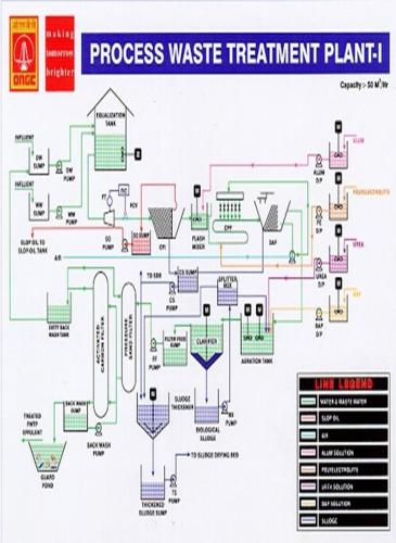
BRIEF DESCRIPTION OF TREATMENT SCHEME:
The effluent treatment facility is designed to handle a flow of 50 m3/hr, and also to produce a treated effluent to conform to the Minimum National Standards. (MINAS).
The treatment scheme has been designed taking into consideration the nature of the different effluent streams, particularly with reference to the nature of flow as well as the characteristics of each individual stream. As far as the flow pattern of various streams including dry weather and wet weather flow is concerned, it will be seen that the streams which are continuous in nature do not add significantly to the pollution load, particularly BOD, phenol, oil and sulphides. Other process streams which are intermittent in nature and limited only for a few hours during the day are also contributing to more or less a similar magnitude. The waste streams namely stream 5, process drain (2 m3/hr) as well as stream no. 6 (1 m3/hr) will contribute more to the sulphide, phenol and BOD load. However, these will get diluted by streams No.7b, and 7c, viz the co-generation boiler blow down as well as LPG boiler blow down contributing about 24 m3/hr (10m3/hr and 14m3/hr respectively) continuous flow. It is worth noting that these streams (No. 7b and 7c) are only contributing to suspended solids and to some extent in raising the temperature of the combined wastewater.
The daily dry weather flow, including intermittent flows shall be about 715 m3/day, out of which about 640 m3/day will be on continuous basis. The characteristics of the waste under this condition will consist of BOD - 47.48 mg/l, oil- 47.83 mg/l, sulphide-2.28 mg/l and phenol about 0.8 mg/l respectively. The hydrocarbons are expected to be partly in free as we; as in emulsified form.
During the monsoon period the contaminated rain water will contribute to BOD as well as hydraulic load. The BOD load will increase from 34.2 kg/day to 187.2 kg/day and hydraulic load from 715m3/day to 1225 m3/day. It is worth noting that the organic load to the plant on daily basis will increase by 3.5 to 4.0 times, whereas the hydraulic load will increase by about 60% to 70%.
The treatment facilities shall comprise of the following main units:
Dry weather and wet weather sump and pump house.
Equalisation tanks.
Cross flow interceptors.
Flash mixers.
CPF/TPF Microflotator (DAF).
Extended aeration type activated sludge process.
Final clarifier.
Filter feed sump and pumps.
Pressure filters.
Activated carbon filters.
Backwash sump and pumps.
Guard pond.
Slop oil sump and pumps.
Chemical sludge sump and pumps.
Biological sludge sump and pumps.
Sludge thickener.
Thickened sludge sump and pumps.
Centrifuge.
The total waste water will be collected in the dry weather sump (100-S-01). During the dry weather, the effluent will be directly pumped at the rate of 30m3/hr to one of the equalization tanks. A constant flow of 25 m3/hr is taken to Cross flow Interceptor unit to remove the free oil to the maximum extent even at very low concentration level and also to ensure more or less a uniform performance under variable hydrocarbon concentration in the waste water. During monsoon, the excess flow to the extent of 135 m3/hr will overflow into the wet weather sump (100-S-02) and pumped to the ‘On-stream’ equalization tank along with dry weather flow. The excess effluent will overflow into the second equalization tank. A constant flow of 50 m3/hr will be withdrawn and both the chains of 25 m3/hr will be in operation till minimum level is reached in the ‘On-stream’ tank. After attaining a minimum level, approx.40 m3/hr flow from the second tank will be taken to the dry weather sump which will overflow into wet weather sump. Effluent from wet weather sump will be pumped to the ‘On-stream’ equalization tank at the rate of 70 m3/hr. During this period, dry weather pumps will not be in operation. A 50 m3/hr flow will be processed through the plant and the excess flow will be accumulated in the tank. This process will go on till the entire content of the second equalization tank is processed. After this the second tank is ready to collect another lot of storm water. Change the controller setting to 25 m3/hr and stop any one chain.
Once the free oil is removed in the cross flow interceptor, the effluent is fed to the chemical treatment section comprising of flash mixer and CPF/TPF Microflotator. This section is mainly provided to take care of emulsified oil and suspended solids. M/s. P.V.Holland has proposed to use alum as coagulant which has been recommended and extensively used in refineries for removal of emulsified oil, and suspended solids from the wastewater. The floating matter on the surface of the TPF unit will be skimmed and taken to the chemical sludge sump along with sludge from the cross flow interceptor unit. The chemical sludge will be collected in a sump and shall be pumped to the thickener. Slop oil which is collected in the slop oil sump will be pumped to slop oil tanks.
The waste water free from the above referred impurities shall be fed into the biological treatment unit incorporating extended aeration type activated sludge process. The required oxygen will be supplied by two 7.5 HP mechanical fixed type surface aerators. Due consideration has been given while designing to the low BOD level as well as high hydraulic load, and provided a holding period of 10 hours to prevent the washout of the biomass. Keeping in view the low BOD input (during dry weather conditions), process is designed on the basis of low level of MLSS in return sludge. This will help in retaining the required biomass in the aeration tank even during the low input of BOD, and shall also help in absorbing sulfide as discharged with the waste water, without hampering the process efficiency. It shall also remove phenol to the required levels specified as per the MINAS. The requisite nutrients Nitrogen and Phosphorous will be added in the form of urea and phosphoric acid. All required nutrients like urea and Phosphoric acid will be added at the inlet of aeration tank. The final clarifier will be provided for separation of the biological solids generated in the system. A separate recirculation sump and pumps are provided for recirculation of requisite quantity of return sludge. The effluent from the clarifier, taken as overflow shall remove the pollutants to the required level, but it is likely to exceed in the suspended solids and COD limits. Therefore, it is proposed to provide tertiary treatment consisting of filtration of this effluent through pressure sand filters followed by activated carbon filters. This tertiary pressure filter units and activated carbon filter units are provided with arrangement for backwashing with treated effluent. A backwash sump & pumps are provided for this purpose. A separate bypass line is provided on the filter outlet, to take the effluent back to the equalization tank, in case it does not meet the required quality criterion because of plant upset or excess process load etc. A filter feed sump with pumps are provided before pressure filters to collect the overflow from final clarifier. The treated effluent will be passed through guard pond (100-T-08) before disposal. The guard pond of 24 Hr capacity is provided as polishing unit.
The excess biological sludge shall be taken to the thickener. Thickened sludge sump and pumps are provided to collect the underflow from thickener and to pump it to the centrifuge. Overflow from thickener and centrate shall be taken back to the inlet of the receiving sump for processing it into treatment plant. Polyelectrolyte dosing facilities are also provided for centrifuge as well as for CPF unit.( Presently, the sludge pumped by sludge transfer pumps are sent to Sludge drying beds instead of centrifuge which is not operational. The liquid filtrate is sent to OWS receiving sump).
PHYSICAL & CHEMICAL TREATMENT:
The physical and chemical treatment facility of the treatment plant is equally divided in two chains each of 25 m3/hr capacity consisting of CFI, Flash Mixer & CPF/TPF units. Only one chain will be in operation during dry weather flow conditions handling total flow of 600m3/day. It is necessary to keep both the chains in working condition by operating each stream alternatively. However, it is necessary to fill water in the non-working unit and the mechanical equipment should be run at frequent intervals as a part of proven maintenance. During heavy rain/excess flow condition both the chains are to be operated in parallel so that effluent at the rate of 50 m3/hr (1200 m3/day) will be processed throughout the plant.(Presently, with the expansion of HGPC in Phases, number of plants have been added leading to excessive flow of waste water. Consequently, the increase in influent hydraulic load is more than the expansions taken up in the ETPs, resulting in both the chains of PWS-I being run continuously all throughout the year.)
The dosing of coagulant and coagulant aid such as Alum & polyelectrolyte is to be decided in the laboratory by carrying out the jar test. For this two chemical solution preparation tanks, each of 12 Hrs capacity is provided for preparing chemical solutions, along with metering pumps for dosing.
At different pH conditions it is necessary to determine the optimum dose of chemical to achieve maximum removal of pollutants.
PROCESS CHEMISTRY
CHEMICAL COAGULATION:
Chemical coagulation is an integral part in the pretreatment of waste water. The chemicals added for chemical precipitation react with substances that are normally present in the waste water. The chemicals used commonly are 1.) Alum. 2.) Ferrous Sulphate (Copperas) 3.) Lime 4.) Sulphuric acid. Alum is used as coagulant for precipitating the suspended solids. When alum is added to waste water, the reaction that takes place is as follows:
Al2 (SO4)318 H 2O + 3 Ca (HCO3)2 à 3Ca SO4 + 2Al(OH) 3 +
6CO2 + 14 H 2O
Alum: Al2 (SO4)318 H 2O ---- ( Mol. Wt :666 )
This reaction results in reduction of bicarbonate alkalinity resulting in reduction of pH of the wastewater. The Aluminium hydroxide is in the form of a gelatinous floc, which settles slowly through the waste water or floats on the surface with fine air bubble. Alum and polyelectrolyte are also dosed to destabilize the oil emulsions and producing other changes.
BIOLOGICAL TREATMENT:
Microorganisms play a very vital role in the biological degradation of the organic matter present in the waste. Bacteria, fungi, algae, protozoa, rotifers, crustaceans and sometimes viruses actively participate in the biological transformation of the organic matter and the end products of the biological degradation are the formation of fresh microbial cells and carbondioxide etc. During this process the organic substances present in the waste, both in the dissolved and suspended and colloidal state are metabolized in presence of air. The biochemical oxygen demand (BOD) of the waste is reduced. Temperature and pH play a vital role in the metabolic activity. Metabolic activity increases with temperature, doubling with every ten degrees centigrade rise in temperature upto a certain limit. The micro-organisms use the carbon, nitrogen, phosphorous and other trace elements, present in the waste, for the synthesis of fresh cells. Most of the industrial waste waters are deficient in the nutrients such as nitrogen phosphorous with the exception of the waste water from food and fermentation group of industries. The waste waters from petroleum and petrochemical industries are deficient in nitrogen and phosphorous. These wastes are rendered amenable for biological treatment by suitable adaptation of the micro-organisms to the organic constituents present in the waste. A culture which is very rich in microbes, which are most active on oils will be developed under field conditions from normal solids which are contaminated with oil.
In case of operation of Activated sludge process, the operation could be classified in two main categories viz. during the development of biomass and for the normal operation of the plant. For development of required biomass in the initial stages, from a running sewage plant add the required quantity of activated sludge or cowdung in the Aeration tank directly to serve as seeding material for fast development of biomass in the tank. Add the required nutrients to meet the requirement of Nitrogen and Phosphorous. The waste water would be added gradually and at the same time the required Oxygen will be supplied by keeping Aerators working. During this stage the process parameters such as inlet and outlet BOD, dissolved oxygen level in the aeration tanks well as the MLSS, MLVSS would be monitored closely. During the biomass development stage the sludge volume index would also be established for this type of effluent. The SVI would also be useful for maintaining the MLSS in the aeration tank. During the normal operation of the treatment plant in both dry weather and wet weather condition the most important aspect in operation of activated sludge process is the maintenance of proper F/M ratio which is achieved by increasing or decreasing MLSS levels in the aeration tank to suit the influent BOD loads. The MLSS in the aeration tank can be regulated by controlling the rate of sludge return base on SVI determined experimentally during operation of the plant. Excess sludge wasting is generally controlled based on experience.
The quick settleability of sludge is an important factor in the efficient performance of the activated sludge plant. The SVI serves also as an index of sludge settleability. Sludge with poor settling characteristics causes bulking, which results in poor effluent due to presence of excessive suspended solids and also in rapid loss of MLSS from Aeration tank. Rising sludge may be due to denitrification in the tank, releasing nitrogen bubbles which buoy up the sludge. The problem can be overcome by increasing the sludge wasting rate.
Even though there would be sufficient oxygen in the aeration tank and the MLSS at the required level, it is of utmost important once to supplement the nutrients to the biomass of the aeration tank. The required nutrients in the form of urea and Phosphoric acid are to be dosed to maintain BOD: N: P ratio, 100:5:1 from the Urea and phosphoric acid solution tanks.
In case the incoming effluent to the aeration tank stops, the aeration should be continued. The aerators should not be stopped. During routine operation of the bio-reactor it is necessary to monitor toxic contents like hydrocarbons and phenols. The other contents like sulphide are indicated at very low level.
TERTIARY TREATMENT:
The tertiary treatment facility comprising of pressure and activated carbon filters are provided mainly to reduce the suspended impurities and COD from the secondary treatment facility. Two chains of each 30 m3/hr capacity are provided consisting of a pressure sand filter followed by activated carbon filter. During wet weather flow conditions, both the chains will be put into operation to treat 50 m3/hr flow. During dry weather flow conditions, both the chains are to be operated alternatively. During normal operation, the second chain will be required to be operated only when first chain is under backwash cycle. As soon as backwash cycle is over, the normal operation should be resumed. Separate backwash sump & pumps are provided downstream of activated carbon filter for this purpose. A guard pond of 24 Hr capacity is provided as polishing unit which helps in getting the effluent polished further. Frequently iodine Nos. of Activated carbon should be checked so as to decide when it is required to be replaced.
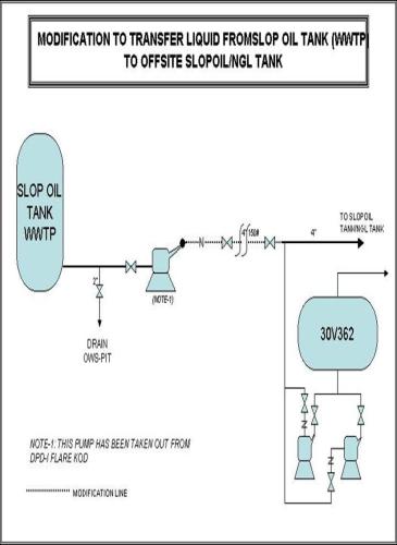
SLOP OIL & SLUDGE HANDLING FACILITY:
A separate sump for slop oil, chemical & oily sludge & biological sludge are provided. Slop oil from CFI unit will be collected by gravity into the slop oil sump & it is pumped by slop oil pumps to slop oil tanks. Sludge from CFI & TPF units is collected in chemical & oily sludge sump and then it is pumped to sludge thickener.
A set of high & low level switches are provided in the sump for giving alarms in control room and for starting the pumps at high level and stopping the pumps at low level for respective sump & pumps.
Underflow from the clarifier is collected in the biological sludge sump and pumped to the splitter box. From the splitter box, required quantity will be lead to Aeration tank & excess will flow to sludge thickener. The quantity of sludge to be recycled should be decided during operation of the aeration tank.
Underflow from the sludge thickener is collected in the thickened sludge sump, and then it is pumped to the centrifuge for dewatering. Overflow from thickener & centrate will go to the receiving sump for further treatment. The sludge cake will be collected in a trolley 7 disposed off. A dosing system for polyelectrolyte is provided and the dose of polyelectrolyte will be determined during operation of centrifuge. (Centrifuge is not in operation now. Instead, the sludge is pumped to sludge drying beds)
PHENOL REMOVAL:
The microbial culture developed will also be suitably acclimatized to degrade phenol, which will be present in low concentration of about 1 mg/l under normal DWF conditions and about 0.5 mg/l under monsoon conditions. Biodegradation of phenol is highly efficient and high removal efficiencies of 98% are feasible even at high phenol content in the incoming waste to the biological treatment system. The microbial degradation of phenol also results in the removal of the BOD contributed by the phenol.
Phenol + O2 (from air) + microbes à New microbial cells + CO2
+ water
SULPHIDE REMOVAL:
The sulphide concentration at inlet of aeration tank is of the order of 1 mg/l. This will be removed in biological treatment to desired final level.
OPERATION OF RECEIVING SUMP (100-S-01)& (100-S-02) PUMPS: (100-P-01 A/B)
OBJECTIVE:
This unit is provided to collect process waste & storm water from the complex and to transfer it to the equalization tank.
DESCRIPTION OF UNIT:
Process and contaminated rain water will enter the dry weather flow portion of the sump (100-S-01). During dry weather condition, effluent from this sump shall be pumped by dry weather pumps (100-P-01 A/B) to equalization tank. During wet weather condition contaminated rain water along with process waste will overflow into wet weather sump (100-S-02) and shall be pumped to equalization tanks by wet weather pumps (100-P-02 A/B/C). The receiving sump is rectangular in shape and divided into two compartments, dry weather sump & wet weather sump. Level switches for high and low level alarm and pump control are provided in both the sumps.
START-UP PROCEDURE:
Clean both the sumps as well as all incoming pipes discharging effluent into the sump.
Check all the valves are operating smoothly and are installed in correct position.
Check all pumps are properly installed in respective position.
Check rotation of pumps and check for any abnormal noise, vibration and overheating etc.
Check oil level in the pumps.
Check all instruments are working properly.
NORMAL OPERATION:
Process waste from the processing complex is collected in dry weather sump, start one of the dry weather pumps to transfer effluent to equalization tank.
High and low level switches are provided in the sump for starting the pump automatically at high level and tripping the pumps at low level. However operate the pumps manually.
Bypass line to cross flow interceptor is provided. However, it is always desirable to operate the plant through equalization tank.
During monsoon period contaminated rain water will overflow into wet weather sump and pumped to ‘On-stream’ equalization tank only. Excess will overflow to other tank.
Excess effluent from second tank shall be taken to receiving sump at the rate of 40m3/hr.
FOR OPERATION PROCEDURE OF PUMPS, PLEASE REFER END PAGES.
OPERATION OF EQUALISATION TANKS: (100-T-01 A/B)
OBJECTIVE:
This unit is provided to equalize and to store excess process waste/storm water.
DESCRIPTION OF UNIT:
Circular vertical storage tanks each of 600 m3 capacity are constructed in carbon steel. Inside surface of the tank shall be epoxy painted.
START-UP PROCEDURE:
Clean the tank.
Check all valves are operating properly.
Check all instruments including flow controller are functioning properly.
Check mixers are working in order.
Keep overflow valve open and close drain valve.
NORMAL OPERATION:
Set the control valve to withdraw 25 m3/hr flow to cross flow interceptor during dry weather condition and operate one chain only. During wet weather flow conditions change the setting to 50m3/hr & operate both the chains.
Allow the tank to fill upto the normal operating level.
See that required quantity of effluent is taken to cross flow interceptor unit by setting flow controller.
Operate one chain or two chains of chemical treatment section depending upon effluent flow rate to the treatment plant.
Always keep one tank empty to receive excess/storm water which will overflow from operating tank.
Withdrawal is constant irrespective of incoming flow. Hence keep inlet valves of operating tank always open and for other tank keep them close.
Always keep mixers ‘On’ for operating tank during withdrawal.
Do not start the mixers until minimum water level is reached in the tank.
SHUT-DOWN PROCEDURE:
Stop outlet valve
Stop mixers
Stop chemical treatment section.
CROSS FLOW INTERCEPTOR:( 100-CFI-01 A/B)
OBJECTIVE:
The cross flow interceptor unit is provided to remove free oil and S.S from effluent by gravity separation.
DESCRIPTION OF UNIT:
The gravity separation is the removal of oils and suspended solids from a water stream by allowing sufficient time in a low velocity basin for the oil droplets to rise to the surface and the solid particles to sink to the bottom.
The corrugated plate interceptor, for which PWT holds the patent, considerably improved this process, by having a large number of corrugated plastic plates assembled as a pack into the separator. The particles only have to travel the distance between the plates to be intercepted. The small plate spacing ensures that flow is always laminar which is essential for gravity separation. The plates are inclined so that the oil collects under the tops of the corrugations and flows upto the surface and the solids slide down the valleys to the bottom of the separator. The corrugated plate packs are mounted in a tank fitted with inlet and outlet weirs, oil skimmer and / or bottom discharge for a solid underflow. The oil skimmer is set so that a layer of oil must build up and flow by gravity from the CPI unit. This prevents water from being skimmed. The geometry of CFI unit is such that overloading (i.e. exceeding the design flow rate) may result in water being skimmed by the oil skimmer but never in oil entering the water discharge system.
OPERATION OF FLASH MIXER: (100-R-01 A/B)
OBJECTIVE:
This unit is provided to mix Alum solution with effluent for denitrification of emulsified oil before it is taken to Dissolved Air Flotation unit.
DESCRIPTION OF UNIT:
This unit is constructed in M.S having bottom entry and overflow outlet. Alum 10% solution is added from solution preparation tank provided in chemical house. For proper contact and mixing of the effluent, a Flash mixer mechanism is provided.
START-UP PROCEDURE:
Check unit is clean and weir is clear.
Check mixer is installed properly.
Check oil in the reduction gear unit. An oil level plug is provided for this purpose.
Check for bolt tightness.
Rotate the shaft by hand to ensure free movements.
Press ‘On’ button and allow the mixer to run dry.
Watch for overheating of the motor, bearings, and reduction gear box. If overheating, check the above points again.
Check direction of rotation of impeller. It should be clockwise when viewed from top.
NORMAL OPERATION:
Top up the oil in the reduction gear box.
Check for overheating of motor, bearing and gear box.
Proper mixing of Alum in required quantity is very much essential for efficient functioning of the process.
Check the doses required for deemulsifing of oil in laboratory.
Adjust the stroke of metering pump and control the Alum dosing.
10% solution of Alum shall be dosed in Flash mixer from solution preparation tank.
SHUT-DOWN PROCEDURE:
Stop the flow to the cross flow interceptor from equalization tank or divert it to second channel.
Switch the motor ‘Off’.
Stop feeding of alum solution or divert it to other flash mixer unit.
Drain the tank if required.
DISSOLVED AIR FLOATATION UNIT: (100-DAF-01 A/B)
OBJECTIVE:
This unit is provided to remove emulsified oil from the effluent.
DESCRIPTION OF UNIT:
COILED PIPE FLOCCULATOR:
Unlike the conventional stirred tank flocculators, the PWT’s CPF flocculator is executed as a plug reactor. The required mixing energy is obtained by energy exchange due to turbulence inside the CPF.
Characteristics of the flocculator are:
Distributing short circuiting and back mixing are avoided.
Residence time distribution is reduced to such an extent that it is approaching the theoretical value of a plug flow system
Optimal and uniform floc growth is obtained as a result of defined velocity gradient.
The resulting floc shows optimal separation efficiency
A polyelectrolyte is dosed into the waste water in the first part of the flocculator. The pipe size is selected to obtain a thorough mixing between the coagulated matter in the waste water and the polyelectrolyte. After the mixing has been completed the pipe size is increased to reduce the mixing intensity (low turbulence) the floc will start growing slowly.
The flocculator is designed so that at the end, the floc has obtained optimum characteristics for interception. In the case of dissolved air flotation is used (DAF), fine air bubbles (Micron sized) are induced in the waste water at several points on the flocculator. Eventually air is induced already before and simultaneous with the polyelectrolyte injection to capture air bubbles in the growing floc. This will give the floc a stable character for air flotation.
TILTED PLATE FLOATATOR (T.P.F.)
The PWT system is based on dissolved air floatation principle whereby the suspended solids and oil globules in the waste water adhere to micron sized air bubbles and float out of suspension. The air bubbles attach to the particles by surface phenomena causing a net reduction of specific gravity.
The micron sized air bubbles are produced by dissolving air into a recycled stream of the TPF effluent at an elevated pressure followed by a subsequent release of pressure through needle valves. The air is introduced from a compressed air supply point into the suction of a multi stage pump. The water is saturated with the air inside the pump and discharged under elevated pressure. When the pressure is reduced through pressure saturators and bubble generators, the air is released as a mass of fine air bubbles.
The air bubbles are released into the waste water stream just before the TPF basin. The big oil and solids attached to the air bubbles, immediately rise to the surface of the water level in the TPF. Slower rising particles and oil droplets are intercepted in the second chamber with PWT’s corrugated plate pack.
The small plate distance of the interceptor and the laminar flow condition within the region create an optimum condition for separation. The slow rising particles are intercepted and collected at the underside of the crests of the corrugations. Because the plates are inclined, the intercepted particles slide upwards, finally leave the plate pack and up to the sludge layer.
A pneumatic driven skimmer device mounted on top of the TPF basin thickens and finally skims off the floated sludge into the sludge holding basin.
The clarified water leaves the plate pack compartment at the lower side, and then flows upwards and out of the TPF basin via overflow weirs.
OPERATION OF AERATION TANK: (100-T-02)
OBJECTIVE:
The objective of Biological treatment is to reduce the dissolved organic matter contributing to BOD & COD by oxidation. Suspended colloidal solids are also reduced in this process.
DESCRIPTION OF UNIT:
The aeration system consists of aeration tanks with RCC platform and fixed type surface aerators. The aeration tank is designed for 50 m3/hr flow rate incorporating an extended aeration type activated sludge process. This represents the completely mixed flow system which shall enable taking even shock organic loads. The inlet and outlet is provided in the form of overflow weirs. Required quantity of nutrients in the form of urea and DAP is dosed at inlet of biological system to meet the requirement of Nitrogen and Phosphorous.
PROCESS CONTROL:
MLSS drops below 3000 ppm: (Mixed liquor suspended solids)
This drop will not occur suddenly but will be indicated by a gradual drop of MLSS value over a period of days. This indicates that bacterial population in the aeration tank is decreasing because of insufficient aeration and insufficient food in incoming flow.
Increase the volume of return sludge pumped, by closing the bleed off valve and ensure that all the sludge is being pumped into FMC-5 and then returns to Aeration tank.
If the MLSS does not still attain the desirable value, the incoming waste has to be analysed for ppm ratio of Nitrogen, phosphorous, carbon and any toxic material.
If BOD, Nitrogen, phosphorous ratio from the desired ratio of 100:5:1 action must be taken to rectify the imbalance by adjusting nutrient dosages.
MLSS grows beyond 5500 ppm:
This phenomenon is due to increased organic loading and reflected by build up in MLSS and above 5500 ppm. As a result of this D.O level goes down and as a result sludge settleability is affected which starts floating on the clarifier surface. This means that the population of bacteria has increased disproportionate to the system requirement. When this takes place, try to reduce the recirculation to very minimum and take the sludge to sludge drying beds.
Stoppages of effluent flow:
If for some reason the flow into the aeration tank stops, the aeration should be continued.
START-UP PROCEDURE:
Press the start button of the aerator ‘On’ for short instant.
Check the direction of rotation of the impeller. It should be clockwise.
Observe that top surface of the impeller is rotating in one plane and the impeller is not wobbling. In case wobbling is observed, it should be corrected by proper balancing at manufacturer’s works.
Observe the agitation in the entire tank. It should be proper and the spray of liquid should be uniform in all the directions.
NORMAL OPERATION:
Press the start button to bring the aerator in operation.
At an interval of five minutes log reading of the ammeter at M.C.C.
If everything is normal aerators are in operation
Check oil level regularly once in a shift and fill the oil to the required level.
Check regularly for overheating and unusual noise in motor and gear box unit.
Always check the submergence level of aerators; it should be 50 mm (Min)
SHUT-DOWN PROCEDURE:
Press the stop button for the aerators and allow the impeller to come to stand-still.
OPERATION OF CLARIFIER: (100-CL-01)
OBJECTIVE:
This unit is provided for the purpose of removing the biological solids from the treated effluent and to recirculate the same to inlet of aeration system to maintain MLSS.
DESCRIPTION OF UNIT:
The clarifier is circular in shape and constructed in RCC. The effluent enters through central column. The mixed liquor is allowed to flow slowly and continuously through the basin from centre to circumference radially. Sedimentation of biologically flocculated solids takes place and clear liquor is collected in peripheral launder. Scraper is moved by rotating bridge which is moved by driven motor. It scrapes the sludge continuously towards sludge pipe.
START-UP PROCEDURE:
Centre Pivot Bearing:
Check the mark on the oil gauge. The oil fill plugs have a vent hole. Be sure that this hole is not closed by paints etc. and is open all the time. Check the oil level and maintain the oil level regularly. Oil to be used is ‘Servomesh-40’ and must be changed every six months.
Sludge Scrapers:
Check clearance between the scrapper blades and tank bottom. It should be in the range of 6 mm to 12 mm at any point (This should be true for the entire tank-bottom surface.)
Slipring Assembly:
Check that slip ring assembly is properly mounted. Open up the cap and ensure that the cable through the centre column is connected to the fixed part of the slip ring assembly and the cables from the traction motor are connected to the carbon bushes.
Traction drive:
Check that the traction wheel bearings are properly greased.
Check for the smooth running of the wheel all alongwith the rails by rotating the bridge manually.
Also ensure that scum scrapper travels smoothly over the scum box. Check that its springs are working.
Check for the right direction of bridge rotation. The arm should rotate clockwise when viewed from the top.
Check the function of pressure switch to cut the motors off.
Now the equipment is ready for service.
NORMAL OPERATION:
During normal operations remove the sludge atleast two to three times during the shift. It is preferable to keep sludge valve crack open and have continuous sludge bleeding.
Have a regular watch on the oil level and re-gearing etc.Check occasionally for over heating and unusual noise and loss of misaligned parts.
OPERATION OF FILTER FEED SUMP (100-P-03 A/B) & PUMPS: (100-P-03 A/B)
OBJECTIVE:
This sump is provided to collect overflow from clarifier and then pumped through pressure sand filter and activated carbon filter for tertiary treatment.
DESCRIPTION OF UNIT:
The sump is rectangular in shape constructed in RCC above ground. Horizontal centrifugal pumps are provided to feed filters.
START-UP PROCEDURE:
Clean the sump and incoming pipes.
Check all valves are operating smoothly and installed in correct position.
Check all pumps are properly installed in respective position.
Check rotation of pump and observe for any abnormal noise, vibration, and overheating.
Check oil level in the pumps.
Check and ensure all instruments are functioning properly.
OPERATION OF SAND FILTERS (100-F-01 A/B) & PUMPS:
(100-P-03 A/B)
OBJECTIVE:
This unit is provided to remove suspended solids from clarifier overflow before it is taken to guard pond through activated carbon filter for final disposal.
DESCRIPTION OF UNIT:
The effluent enters from top and comes out from bottom. Arrangement for air scouring and backwashing with treated water is provided. Flow indicators are provided for measuring feed flow, backwash flow and air flow. For air scouring plant air is to be used. Pressure reducing valve is provided to reduce the plant air pressure. Backwashing of filters will be required to be carried out when pressure drop across a filter increases more than 0.8 kg/cm2 g or once in 24 hours.
START-UP PROCEDURE:
Check all the valves for smooth operation.
Check that all instruments are functioning properly.
Make sure that sand is properly filled to required level.
First backwash the filters as per backwashing procedure before taking the filters into operation.
Start one of the filter feed pumps 100-P-03 A/B and slowly open the inlet valve of the filter to be taken into operation. By doing so air inside the filter will get replaced with effluent.
When complete air has been replaced by effluent slowly open the outlet valve of the filter.
Check for any leakage from the filter nozzle, piping, valves etc.
Close vent valve when complete air is vented.
Thus the filter is in operation.
SHUT-DOWN PROCEDURE:
Take the standby filter into operation or close the pumps 100-P-03 A/B as per requirement.
Close the inlet valve of the filter, and then close the outlet valve of the filter.
The filter can be drained by opening the drain valve. At the time of draining, vent valve should be kept open.
BACKWASHING:
Backwashing is required when lot of solids has got settled in the filtering sand. This gives large resistance to the flow of effluent and pressure drop across the filter increases. Filters are to be backwashed if pressure drop exceeds 0.8 kg/cm2.
Filters should be backwashed after every 24 hours.
The backwashing is to be done by treated effluent and air scouring by plant air.
Isolate the filter to be backwashed by closing inlet and outlet valves.
Open drain valve and drain the filter.
Open air inlet valve and outlet valve for air scouring.
Admit the air to pass through the bed for about 5 minutes.
After air scouring is over, close air inlet and outlet valve.
Start one of the backwash pumps 100-P-04 A/B.
For water backwashing, open backwash inlet valve and outlet valve.
Allow the water to pass through bed for about 10 minutes.
Backwashed water will go to inlet receiving sump through drain.
Keep checking the backwash outlet for clarity.
Backwashing is to be stopped when backwashed water becomes clear.
After completing backwashing of the unit close backwash inlet and outlet valve.
Open drain valve for draining the filter.
For rinsing the bed, open effluent inlet valve and allow water for about 5 to 10 min. at 25 m3/hr flow rate.
After rinsing, close drain valve and open filtered water outlet valve to take filter into operation or close inlet valve and keep filter ready to take into operation whenever required.
Each filter is required to be backwashed, once in a day irrespective of built up of pressure differential.
OPERATION OF ACTIVATED CARBON FILTERS: (100-CF-01 A/B)
OBJECTIVE:
This unit is provided to remove COD from the filtered water from pressure sand filter before it is taken to Guard pond.
DESCRIPTION OF UNIT:
The unit is a vertical pressure vessel, fabricated from carbon steel plates. The effluent enters from the top and comes out from the bottom. Air scouring and backwash system is same as that of pressure sand filters. Washing with L.P steam with pressure reducing valve is provided as additional facility for activated carbon filter units.
START-UP PROCEDURE:
Check all the valves for smooth operation.
Check that all instruments are functioning properly.
Make sure that sand is properly filled to required level.
First backwash the filters as per backwashing procedure before taking the filters into operation.
Start one of the filter feed pumps 100-P-03 A/B and slowly open the inlet valve of the filter to be taken into operation. By doing so air inside the filter will get replaced with effluent.
When complete air has been replaced by effluent slowly open the outlet valve of the filter.
Check for any leakage from the filter nozzle, piping, valves etc.
Close vent valve when complete air is vented.
Thus the filter is in operation.
SHUT-DOWN PROCEDURE:
Take the standby filter into operation or close the pumps 100-P-03 A/B as per requirement.
Close the inlet valve of the filter, then close the outlet valve of the filter.
The filter can be drained by opening the drain valve. At the time of draining, vent valve should be kept open.
BACKWASHING:
Backwashing is required when lot of solids has got settled in the filtering sand. This gives large resistance to the flow of effluent and pressure drop across the filter increases. Filters are to be backwashed if pressure drop exceeds 0.8 kg/cm2.
Filters should be backwashed after every 24 hours.
The backwashing is to be done by treated effluent and air scouring by plant air.
Isolate the filter to be backwashed by closing inlet and outlet valves.
Open drain valve and drain the filter.
Open air inlet valve and outlet valve for air scouring.
Admit the air to pass through the bed for about 5 minutes.
After air scouring is over, close air inlet and outlet valve.
Start one of the backwash pumps 100-P-04 A/B.
For water backwashing, open backwash inlet valve and outlet valve.
Allow the water to pass through bed for about 10 minutes.
Backwashed water will go to inlet receiving sump through drain.
Keep checking the backwash outlet for clarity.
Backwashing is to be stopped when backwashed water becomes clear.
After completing backwashing of the unit close backwash inlet and outlet valve.
Open drain valve for draining the filter.
For rinsing the bed, open effluent inlet valve and allow water for about 5 to 10 min. at 25 m3/hr flow rate.
After rinsing, close drain valve and open filtered water outlet valve to take filter into operation or close inlet valve and keep filter ready to take into operation whenever required.
Each filter is required to be backwashed, once in a day irrespective of built up of pressure differential.
OPERATION OF BACKWASH SUMP (100-S-04) AND PUMPS: (100-P-04 A/B)
OBJECTIVE:
This unit is provided to store required quantity of treated effluent for backwashing pressure sand filters and activated carbon filters.
DESCRIPTION OF UNIT:
The sump is rectangular in shape, constructed in RCC partly underground and partly above ground. Horizontal centrifugal pumps are provided for pumping treated effluent for backwashing the filters.
START-UP PROCEDURE:
Clean the sump and incoming pipe and outgoing pipe.
Check all valves are operating smoothly and installed in correct position.
Check all pumps are properly installed in respective position.
Check rotation of pump and observe for any abnormal noise, vibration, and overheating.
Check oil level in the pumps.
Check and ensure all instruments are functioning properly.
OPERATION OF GUARD POND: (100-T-08)
OBJECTIVE:
The guard pond is provided to collect treated effluent of uniform quality before final disposal.( Originally, it was a single large guard pond of 1200 m3 capacity, but for the sake of maintenance purposes, it was divided into two sections by building a separation wall in the middle.)
DESCRIPTION OF UNIT:
The effluent from Activated carbon filter is fed to backwash sump and overflow from backwash sump is taken to guard pond. Effluent from this pond passes through flow measuring channel before it is disposed off. A surface aerator is provided in each of the guard pond I & II which runs continuously supplying oxygen to the stored effluent. The pond is constructed in earthen embankment with concrete lining.
NORMAL OPERATION:
Observe flow pH and D.O of treated effluent.
In case if treated effluent is not in conformity with effluent discharge standards, divert the effluent to receiving sump for processing.
If it is meeting the quality, discharge it to common sump for disposal.
SHUT-DOWN PROCEDURE:
Stop the incoming effluent.
OPERATION OF BIOLOGICAL SLUDGE SUMP (100-S-06) AND PUMPS:(100-P-06 A/B)
OBJECTIVE:
This unit is provided to collect underflow from clarifier and to recirculate back to Aeration tank and excess sludge will go to sludge thickener.
DESCRIPTION OF UNIT:
This unit is rectangular in shape and constructed in RCC underground unit attached to the clarifier unit. Vertical pumps are provided on top of sump for pumping biological sludge to splitter box.
START-UP PROCEDURE:
Clean the sump and incoming pipes.
Check all valves are operating smoothly and installed in correct position.
Check all pumps are properly installed in respective position.
Check and ensure all instruments are functioning properly.
FOR PUMP OPERATION PLEASE SEE END PAGES.
OPERATION OF SLOP OIL SUMP (100-S-08)AND
PUMPS:(100-P-08 A/B)
OBJECTIVE:
To collect slop oil skimmed from cross flow interceptor and to transfer the same to slop oil tanks located in contaminated rain water treatment plant area.
DESCRIPTION OF UNIT:
The sump is rectangular in shape and constructed in RCC partly underground and partly above ground. Progressive cavity type positive displacement pumps are provided to transfer slop oil to slop oil tanks.
OPERATION OF CHEMICAL SLUDGE SUMP (100-S-05) AND PUMPS:(100-P-05 A/B)
OBJECTIVE:
This unit is provided to collect chemical and oily sludge from cross flow interceptor units and dissolved air floatation unit and to transfer it to sludge thickener unit.
DESCRIPTION OF UNIT:
The sump is rectangular in shape and constructed in RCC partly underground and partly above ground. Progressive cavity type positive displacement pumps are provided to transfer chemical sludge to sludge thickener.
OPERATION OF SLUDGE THICKENER:(100-ST-01)
OBJECTIVE:
The purpose of this unit is to thicken the chemical as well as biological sludge so as to reduce the volume of sludge and increase the solid concentration of the sludge from 1% consistency to 1 ½ % to 3 % consistency.
DESCRIPTION OF UNIT:
Chemical and oily sludge from the sump is pumped by progressive cavity pumps to feed well of sludge thickener. Excess biological sludge from splitter box shall be fed to feed well under gravity.
The sludge thickener is circular in shape and constructed in RCC. The underflow from thickener is taken to thickened sludge sump and overflow from thickener is taken to receiving sump.
PROCEDURE FOR START-UP, NORMAL OPERATION AND SHUT-DOWN IS SIMILAR TO THAT OF CLARIFIER MECHANISM.
OPERATION OF THICKENED SLUDGE SUMP (100-S-07)AND PUMP:(100-P-07 A/B)
OBJECTIVE:
This unit is provided to collect thickened sludge from sludge thickener and to pump it to centrifuge for dewatering. (Presently, the sludge is sent to sludge drying beds where water trickles down and get carried away to inlet sump of OWS. The sludge becomes cake on drying which is removed and shifted to sludge lagoon where it will be analyzed for pH and other heavy metals before it is dispatched to designated landfill stations. The sludge in sludge lagoon will be treated with lime to bring the pH within the limits for disposal.)
DESCRIPTION OF UNIT:
The sump is rectangular in shape and constructed in RCC. Progressive cavity type positive displacement pumps are provided to transfer thickened sludge to centrifuge.
FOR OPERATION OF POSITIVE DISPLACEMENT PUMPS, PLEASE REFER UNDER ‘SLOP OIL SUMP AND PUMPS’
PUMPS OPERATION: (CENTRIFUGAL)
START-UP PROCEDURE:
a) Check that the equipment, instrument, valves and piping are secured and in proper alignment.
b) Charge bearings to the level marked, with the oil of correct grade. Do not overfill.
c) Turn unit by hand to ensure that the movement of the pump and drive shaft free.
d) Make sure that the discharge check valve is not leaking.
e) Make sure that the discharge valve is closed, the suction valve is wide open and a full supply to the suction is assured. A fully open suction valve ensures full priming.
f) Check that the priming fluid has filled up the pump casing.
g) Start the pump by pressing the adjoining start button ‘On’.
h) Note the reading on the discharge gauge. It should show normal discharge pressure for the pump.
i) Open the discharge valve gradually to full open position.
j) If every thing is O.K. the pump is now in normal operation.
NORMAL OPERATION:
a) Allow each pump to work atleast once in a shift. Watch the pressure regularly and see that the operating pressure is in normal range.
b) Log the reading of the pump discharge pressure gauge at specified intervals. Preferably at an interval of half an hour.
c) Check the bearing lubricating oil level regularly.
d) Check pumps glands and bearings for overheating, leaking etc.
e) Watch for leaks in the system and take immediate action for rectification.
f) Watch for loose mechanical parts, misalignment and any unusual noise in the system.
SHUT-DOWN PROCEDURE:
a) Close the discharge shut off valve of the pump in operation
b) Press the stop button of the pump and allow it to come to a standstill.
c) Leave the suction valve, open unless any maintenance is required.
EMERGENCY OPERATION: Procedure to put standby pump in operation:
a) Follow steps (a), (b), and (c) of the shut down procedure for the pump to be stopped if necessary.
b) Press the start button ‘On’ to start the standby unit.
c) Watch the discharge pressure on the gauge. It should be normal.
d) Open discharge valve gradually and leave it wide open.
e) If every thing is O.K. the standby pump is in normal operation.
OPERATION OF PUMPS: (POSITIVE DISPLACEMENT – SCREW PUMP):
START-UP PROCEDURE:
Check that the equipment, instrument, valves and piping are secured and in proper alignment.
Never run the pump in a dry condition even for a few revolutions or the stator will immediately be damaged
Pumps must be filled with liquid before starting, filling plugs are provided for this purpose.
Initial filling is not for priming purpose, but to provide the necessary lubrication of the stator while the pump primes itself.
When pumps are stopped sufficient liquid will normally trapped in rotor /stator assembly to provide lubrication upon restarting.
If the pump has been left standing for an appreciable time or dismantled and reassembled it must be refilled with liquid and given a few turns by hand owing to the interference fit of Rotor/Stator. However, this stiffness disappears when pump is running normally against pressure.
Check rotation of these pumps are suitable in either direction. Looking on the drive end counter clockwise rotation will cause the branch nearest to the drive end to be the inlet conversely, clockwise rotation will make this same branch the outlet.
Check the rotation of motor before coupling the pumps to prevent dry running of pump.
Start the pump by pressing the adjoining start button ‘On’.
Note the reading on the discharge gauge. It should show normal discharge pressure for the pump.
If every thing is O.K the pump is now in normal operation.
NORMAL OPERATION:
Keep suction valve (provided if suction is flooded) always open. Do not provide foot valve or suction valve if suction is negative. These pumps are self priming pumps.
Keep delivery valve open of the pump to be operated and start the pump. Do not start the pumps against a closed inlet and outlet valves.
Do not vary the flow rate by throttling suction or delivery valves.
Never exceed recommended pump speed.
Do not reverse the direction of pumps without consulting pump manufacturer, this will change suction to delivery and delivery to suction.
Do not tighten glands when pump is in operation.
Allow each pump to work atleast once in a shift. Watch the pressure regularly and see that the operating pressure is in normal range.
Log the reading of the pump discharge pressure gauge at specified intervals, preferably at an interval of about half an hour.
Check pump’s glands and bearings for overheating, leaking etc.
Watch for leaks in the system and take immediate action for rectification.
Watch for loose mechanical parts, misalignment and any unusual noise in the system.
SHUT-DOWN PROCEDURE:
First stop the pump & then close delivery valve.
Press the stop button of the pump and allow it to come to a standstill.
Leave the suction valve open, if provided, and close delivery valve.
EMERGENCY OPERATION:
Procedure to put a standby pump in operation:
Follow the shut down procedure for the pump to be stopped if necessary.
Press the start button ‘On’ to start the standby unit.
Watch the discharge pressure on the gauge. It should be normal.
If every thing is O.K. the standby pump is in normal operation.
OPERATION OF METERING PUMPS:
START UP PROCEDURE
MAIN CHECK-UPS
Before commissioning a pump or set of pumps please ensure to carefully make, interalia, the following two (2) checks –
LUBRICATING OIL
Select correct grade of lubrication oils :
Fill such oil in the Crank Case Body upto the Centre line of the oil indication window: and among other things.
Please ensure that the oil level is not higher than the prescribed limit as otherwise the motor/prime mover is likely to get over-loaded.
FIRST OIL CHANGE should be between the first 95-100 hours running-in and thereafter the oil should be changed between 475-500 hours of working
DIRECTION OF ROTATION
Direction of rotation must be as per the arrow mark shown on the pump as otherwise the pump would be damaged. In case of the arrow mark is not visible or cannot be located, determine the direction of rotation as under:-
If you face the pump by keeping the LIQUID/WET END on your left hand side and the metering knob on your right hand side, the direction of rotation of pump should be deemed as CLOCKWISE.
GLAND PACKING
The liquid end is packed with an appropriate type of packing selected according to the liquid to be handled and its pressure and temperature etc. In case any leakage is found through seals, stop the pump and tighten gland nut with hand or an appropriate rod, through one eighth turn. Then start the pump. If you still find the slightest leakage, watch it for about 20 minutes. If the leakage still continues then repeat the same procedure. Please note that over tightening of the gland would damage the seals and plunger.
STROKE ADJUSTMENT
A WELORE pump is equipped with micrometer type metering knob through which you can adjust the stroke length of the plunger from 0 to 100% to adjust its capacity. Please note that the stroke should not be increased by more than 100% as it is likely to damage some major and critical/sensitive part of the pump. Graduation of the adjustment knob is calibrated with accuracy in percentage of the total strokes. Prior to each adjustment of the pump capacity, please do not forget to loosen the locking system and to retighten it after the adjustment of capacity.
CAPACITY CALIBRATION:
Trial runs may be made in order to determine the exact capacity of the pump under actual operating conditions. Usually, it is only necessary to calibrate the pump at 3 different stroke lengths in order to determine the characteristics throughout the all ranges of calibration. The settings normally used are the capacity rate at maximum stroke length, at 50% and at 10% of stroke length. The following methods may be used to measure the capacity rates.
Measure the level drop in a calibrated tank located at pump suction and/or
Measure at discharge side of the pump the quantity delivered at the outlet.
For dangerous liquids, it is recommended to use exclusively the firs method since it prevents the operator from coming into contact with the fluid being handled.
STARTING OF DIAPHRAGM PUMPS:
Fill the replenishing chamber with hydraulic fluid.
Start the pumps.
Push oil compensation valve for few strokes. This should be continued until air bubbles disappear.
If there is any change in the required discharge pressure the set pressure of oil relief valve should be readjusted.