Welcome to ONGC Hazira Plant Intranet
CONTENTS PAGE NO.
1) SECTION-1 - GENERAL
1.0 Introduction 01
1.1 Plant Capacities 01
1.2 Stream Hours & Turnaround Ratio 01
1.3 Feed Stock 02
1.4 Products 03
1.5 Estimated Utilities Consumption 04
1.6 Equipments List 04
2) SECTION-2 – PROCESS DESCRIPTION
2.1 General 09
2.2 Feed Gas Supply 10
2.3 Feed Gas Cooling & Drying 11
2.4 Feed Gas Chill Down 13
2.5 Lean Gas Compression & Despatch 17
2.6 Condensate Handling System 18
2.7 Feed Liquid Drying 19
2.8 Dryers Regeneration 22
2.9 Residue Gas Compression 24
2.10 Light Ends Fractionator 25
2.11 LEF Overhead Expander Compressor 27
2.12 LPG Column 29
2.13 Propane Column 30
2.14 Refrigeration System 32
2.15 Flare & Blow down System 34
2.16 Utility System 35
2.17 Control Room 39
2.18 Process Flow Diagram 40
Effluent System Layout 41
2.19 Emergency Procedures 42
3) SECTION-3 – OPERATING PROCEDURES
3.1 Introduction 43
3.2 Start Up 43
3.3 De-Icing 70
3.4 Shutdown 70
3.5 Emergency Procedures 75
3.6 Samples & Tests 81
4) SECTION - 4 - ANNEXURES
Annexure-I: Operating Parameters 85
Annexure-II: List of Alarms and Trips 90
Annexure-III: Regeneration & Fuel Gas Composition 99
Annexure-IV:(Material Balance as per Design) 100
Annexure-V: Requirements For LPG (IS: 4576-1978) 109
Annexure-VI: Forthcoming Projects in LPG Plant 111
CONTENTS PAGE NO.
5) SECTION – 5
Special Features and Modifications 113
Schematics of different modifications 114
SECTION – I
GENERAL
1.1 INTRODUCTION:
Oil and Natural Gas Corporation Ltd. Of
The Plant is designed to process 20 MMNM3/day of gas and associated condensate (in Phase-I & II). The gas and associated condensate are received at the Plant from the Offshore platforms in
Hazira Plant consists of Gas/ Condensate Terminal facility, Gas Sweetening, Gas Dehydration, Condensate Fractionation, Condensate Stabilisation (presently not being used), Dew Point Depression, Kerosene Recovery, Sulphur Recovery Units & LPG Recovery Plant. Feed to LPG Recovery unit is taken from downstream of Gas Sweetening Unit.
LPG recovery plant is designed to process 5 MMNM3/day of sweet gas. The balance gas (33.5 MMNM3/day) after routing it through gas dehydration dew point depression units will be supplied to various fertilizer plants along the 1500 km long pipeline route from Hazira to Jagdishpur (HBJ pipeline) in U.P. The condensate collected in the dew point depression units is also processed in LPG recovery plant.
The process for LPG recovery involves expansion and consequent cooling of gases to produce condensate, which is distilled to give LPG & Aromatic Rich Naptha. The Lean Gas is supplied at two pressure levels to the consumer plants.
Propane refrigeration is used to supplement the total refrigeration requirement. A central flare and utility system is provided for the entire Plant that will cater to the LPG recovery unit also.
1.2 PLANT CAPACITIES:
The plant is designed to process 5.0 MMNM3/day of sweet gas along with average amount of Hydrocarbon condensate corresponding to three Dew point depression trains, which are a part of the Gas Processing Plant.
1.3 STREAM HOURS AND TURNDOWN RATIO:
Plant is designed for 8000 operating hours every year. The plant is designed to operate upto a turndown of 30% with respect to throughput.
1.4 FEEDSTOCK:
1.4.1 FEEDSTOCK SOURCE AND FLOW RATE:
1.4.1.1.1 Gaseous Feedstock:
5.12 MMNM3/day free gas from
OR
5.12 MMNM3/day associated gas from Bombay High Offshore field.
1.4.1.2 Liquid Feedstock:
Average amount of condensate generated in 3 Dew point depression units (upto 40 M3/hr) (presently 7 to 8 trains equivalent to 2300 m3/day)
OR
Pipeline condensate corresponding to 5.12 MMNM3/day of associated gas from Bombay High (presently sweet condensate is not being received).
1.4.2 FEEDSTOCK COMPOSITION:
Feed stock composition at plant battery limit is as per Table-1. The free gas specification is based on Gas Sweetening facilities design. The condensate specification is based on Dew point depression unit design. The associated gas composition is based on simulation studies carried out in August 1981 for complete Bombay High facilities.
TABLE 1.0
COMPONENTS | ASSOCIATED GAS | FREE GAS | DPD CONDENSATE | ||
SIMULATED | SIMULATED | PRESENT | SIMULATED | PRESENT | |
N2 | 0.21 | 0.01 | 0.0 | -- | 0.93 |
H2S | -- | 4 ppm | <4 ppm | -- | -- |
CO2 | 1.89 | 5.12 | 5.35 | 4.59 | 1.12 |
C1 | 80.23 | 79.72 | 80.87 | 37.60 | 31.42 |
C2 | 9.00 | 7.66 | 7.5 | 11.86 | 14.08 |
C3 | 5.50 | 4.67 | 4.11 | 16.57 | 18.56 |
iC4 | 0.93 | 0.88 | 0.76 | 5.36 | 7.04 |
nC4 | 1.23 | 1.10 | 0.90 | 8.23 | 9.00 |
iC5 | 0.24 | 0.26 | 0.34 | 3.22 | 3.40 |
nC5 | 0.38 | 0.25 | 0.07 | 3.52 | 2.03 |
nC6 | 0.39 | 0.17 | 0.1 | 3.67 | 3.55 |
nC7 | -- | 0.09 | 2.75 | 8.87 | |
nC8 | -- | 0.05 | 1.81 | ||
nC9 | -- | 0.013 | 0.50 | ||
nC10 | -- | 0.004 | 0.16 | ||
nC11 | -- | 0.003 | 0.09 | ||
nC12+ | -- | 0.02 | |||
TOTAL | 100.00 | 100.00 | 100.00 | 100.00 | 100.00 |
* Values are in mole %.
1.5 PRODUCTS:
1.5.1 PRODUCT SPECIFICATIONS:
1.5.1.1 LPG: The plant is designed to extract LPG from the feed gas and condensate. Specifications of LPG will be 50:50 by wt.(approx.) of C3:C4 and will conform to IS-4576 for marketing system. Vapor pressure of LPG=16.87 Kg/cm2a (max) at 45 OC.
1.5.1.2 ARN: By product Aromatic Rich Naptha is a mixture of pentane and heavier hydrocarbons as present in feed streams. Vapor pressure=0.9 Kg/cm2a (max) at 40 OC.
1.5.1.3 Lean Gas: Composition of Lean Gas from LPG recovery facility will depend on the feed gas composition and is expected to vary with time. However, a typical Lean Gas composition is given in Table 1.1.
TABLE 1.1
COMPONENT | HP LEAN GAS (MOLE%) | LP LEAN GAS (MOLE%) | ||
SIMULATED | PRESENT* | SIMULATED | PRESENT | |
N2 | 0.01 | 0.0 | -- | -- |
H2S | 4 ppm | 2 ppm | -- | -- |
CO2 | 4.76 | 5.01 | 9.02 | 9.40 |
C1 | 88.43 | 87.98 | 61.59 | 60.42 |
C2 | 5.52 | 5.54 | 22.52 | 24.63 |
C3 | 1.18 | 1.35 | 6.86 | 5.53 |
iC4 | 0.06 | 0.12 | 0.01 | 0.02 |
nC4 | 0.04 | -- | -- | -- |
TOTAL | 100.00 | 100.00 | 100.00 | 100.00 |
* Above composition is without LP Gas mixing. By operating Residue Gas Compressor due to addition of richer LP Lean Gas the composition will change.
1.5.2 PRODUCTION POTENTIAL:
LPG : 220,000 TPA (design)
: 289,220 TPA approx. (at present)
ARN : 102,000 TPA (design)
: 213,840 TPA approx. (at present)
LEAN GAS : 2.2 MMNM3/day (design)
: 4.6 MMNM3/day approx.(at present)
Lean gas is supplied as high pressure Lean Gas to KRIBHCO and presently to IPCL-Dahej & thereafter, to other consumers. 0.6 MMNM3/day as design (presently, 0.66 MMNM3/day) lean gas is supplied as low pressure lean gas to KRIBHCO. Rest of the lean gas after internal fuel consumption of the entire Plant is supplied to other consumers.
LPG recovery efficiency depends upon the operating pressure. At lower pressures, LPG production is correspondingly less.
1.6 UTILITIES CONSUMPTION:
UTILITY | DESIGN | UNITS | ACTUAL (MAX.) | |
NORMAL | MAXIMUM | |||
LP STEAM (IAEC) | -- | 4.0 | T/Hr | 17 |
LP STEAM (Cogen.) | -- | -- | T/Hr | |
MP STEAM | 15.9 | 19.7 | T/Hr | 8.5 |
COOLING WATER | 2425 | 2700 | M3/Hr | NW |
INSTRUMENT AIR | 600 | 600 | NM3/Hr | NA |
PLANT AIR | 170 | 170 | NM3/Hr | NA |
INERT GAS | 50 | 220 | NM3/Hr | NA |
FUEL GAS | 750 | 900 | Kg/Hr | 326 (M3/hr) |
1.7 EQUIPMENT LIST WITH BROAD SPECIFICATIONS
A) VESSELS:
S. No. | Equip- | Equipment Name | BROAD SPECIFICATIONS | |||
O.D. (mm) | Height Length (mm) | Type | Material OfConstruction | |||
1) | V-101 | Feed Gas K.O.Drum | 3200 | 6000 | V | C.S. |
2) | V-102 | Feed Gas Separator-I | 3200 | 7500 | V | Charpy C.S. |
3) | V-103 | Feed Gas Separator-II | 3400 | 5200 | V | Alloy Steel/ S.S |
4) | V-104 | Lean gas compressor suction K.O.Drum | 3800 | 5300 | V | C.S. |
5) | V-105 | LEF O/H Exp.-Comp. K.O.Drum | 2300 | 3750 | V | Charpy C.S. |
6) | V-106 | Regeneration Gas Moisture Separator | 2100 | 3600 | V | C.S. |
7) | V-107 | Residue Gas compressor discharge K.O.D | 1500 | 3650 | V | C.S. |
8) | V-108 | LEF Reflux Drum | 2100 | 5100 | V | C.S. |
9) | V-109 | LPG Reflux Drum | 1600 | 4800 | H | C.S. |
10) | V-110 | Propane Reflux Drum | 1500 | 4200 | H | C.S. |
11) | V-111 | LEF Condensate Pot | 1000 | 2150 | V | C.S. |
12) | V-112 | LPG Condensate Pot | 1000 | 2150 | V | C.S. |
13) | V-113 | Propane Column Condensate Pot | 1000 | 2150 | V | C.S. |
14) | V-114 | Liquid Dryer Drain Collection Drum | 2000 | 5550 | H | C.S. |
15) | V-115 | Condensate Surge Drum | 2800 | 7000 | H | C.S. |
16) | V-117 | Propane Refrigeration Accumulator | 1600 | 4500 | H | C.S. |
17) | V-118 | Propane Refrigeration Economiser | 1600 | 5600 | V | C.S. |
18) | V-119 | Propane 2nd Stage Suction Drum | 1600 | 3450 | V | C.S. |
19) | V-120 | Propane 1st Stage Suction Drum | 2600 | 4450 | H | Charpy C.S. |
20) | V-121 | Fuel Gas K.O.Drum | 1600 | 3450 | V | C.S. |
21) | V-122 | Flare K.O.Drum | 4500 | 11000 | H | Charpy C.S. |
22) | V-123 | Blow Down Drum | 2400 | 4550 | V | S.S. |
23) | V-124 | Instrument Air Receiver | 2300 | 5750 | V | C.S. |
24) | V-201 | LP condensate flash drum | 1000 | 3100 | V | C.S |
25) | V-202 | MP condensate flash drum | 1600 | 3600 | V | C.S. |
26) | V-207 | Methanol Pot | 2000 | 4000 | V | C.S. |
27) | V-212 | U/G Methanol Drum | 2500 | 5000 | H | C.S |
28) | V-213 | MP condensate flash drum | 1600 (I.D.) | 3650 | V | C.S. |
29) | V-214 | Contaminated condensate flash drum | 1000 | 2500 | V | C.S. |
B) HEAT EXCHANGERS:
S. No. | Equip- | Equipment Name | BROAD SPECIFICATIONS | ||
Heat Duty MMKcal/ Hr | Material of Construction | ||||
Shell | Tube | ||||
1) | E-101 | Feed Gas Chiller | 8.973 | Brazed Al. Construction | |
2) | E-102A/B | Lean gas Exp-Comp After cooler | 0.780 | c.s. | c.s. |
3) | E-103A/B | Lean gas compressor after cooler | 1.120 | c.s. | c.s. |
4) | E-104 | Regeneration gas cooler | 5.500 | c.s. | c.s. |
5) | E-105 | Residue gas comp. after cooler | 2.490 | c.s. | c.s. |
6) | E-106 | LEF Condenser | 1.870 | Charpy C.S. | Charpy C.S. |
7) | E-107 | LEF Reboiler | 4.300 | c.s. | c.s. |
8) | E-108 | LPG Column Condenser | 4.040 | c.s. | c.s. |
9) | E-109 | LPG Column Reboiler | 2.990 | c.s. | c.s. |
10) | E-110 | ARN Cooler | 0.850 | c.s. | c.s. |
11) | E-111 | Propane column Condenser | 0.870 | c.s. | c.s. |
12) | E-112 | Propane column Reboiler | 1.030 | c.s. | c.s. |
13) | E-113 | Propane column bottom cooler | 0.160 | c.s. | c.s. |
14) | E-115 | Condensate Heater | 0.623 | c.s. | c.s. |
15) | E-118A/B | Propane Refrigeration Condenser | 3.290 | c.s. | c.s. |
16) | E-119 | 2nd stage Propane vaporizer | 0.150 | c.s. | c.s. |
17) | E-120 | 1st stage Propane vaporizer | 0.290 | Charpy c.s. | Charpy c.s. |
18) | E-121 | Blow down Vaporiser | 0.562 | c.s. | c.s. |
19) | E-122 | Feed Gas Cooler | 1.790 | c.s. | c.s. |
20) | E-123 | LEF O/H Exp-Comp after cooler | 0.140 | c.s. | c.s. |
21) | E-124 | Pipeline Fuel Gas Heater | 0.185 | c.s. | c.s. |
22) | E-125 | Seal Gas Heater | 0.011 | c.s. | c.s. |
C) COLUMNS:
S. No. | Equip- | Equipment Name | BROAD SPECIFICATIONS | |||||
O.D. (mm) | Height (mm) | No. of Trays | Material OfConstruction | |||||
She-ll | Tray | Valv-es | ||||||
1) | C-101 | Light Ends Fractionator | 36900 | 50 | C.S | C.S | C.S | |
Upper Section | 2000 | 34000 | ||||||
Lower Section | 3400 | 34000 | ||||||
4) | V-104 | LPG Column | 2000 | 37400 | 54 | C.S | C.S | S.S |
5) | V-105 | Propane Column | 1200 | 25500 | 35 | C.S | C.S | S.S |
D) PUMPS:
S. No. | Equip- | Equipment Name | BROAD SPECIFICATIONS | ||||
Type | RatedCap. M3/hr | Head (M) | Material of Construction | ||||
Casing | Impell-er | ||||||
1) | P-101A/B | LEF Reflux Pumps | Centri-fugal | 47.7 | 102.9 | C.S. | C.S. |
2) | P-102A/B | LPG Column Reflux & Transfer Pumps | -do- | 110.4 | 176 | C.S. | C.S. |
3) | P-103A/B | Propane Column Reflux Pumps | -do- | 32 | 100 | C.S. | C.S. |
4) | P-104A/B | Propane Product Transfer Pumps | -do- | 3.03 | 48.4 | C.S. | C.S. |
5) | P-105A/B | Drain Liquid Recovery Pumps | -do- (Barrel Type) | 10 | 51.1 | CharpyC.S. | CharpyC.S. |
6) | P-106A/B/C | Condensate Transfer Pumps | -do- | 47 | 144 | C.S. | C.S. |
7) | P-107A/B | Refrigeration Propane Transfer Pumps | -do- | 5 | 336 | CharpyC.S. | CharpyC.S. |
8) | P-108A/B | Feed Gas K.O. Condensate Pumps | -do- | 5 | 88.9 | C.S. | C.S. |
9) | P-115A/B | MDEA Disposal Pumps | -do- | 2 | 11 | C.S. | C.S. |
10) | P-116A/B | TEG Disposal Pumps | -do- | 0.2 | 9 | C.S. | S.S. |
11) | P-211 | Methanol-Offsite Transfer Pump | -do- (submersible | 10 | 33.25 | C.S. | C.S. |
12) | P-212A/B | Methanol Injection Pumps | Recipro-cating | 4 | -- | C.S. | S.S. |
13) | P-217A/B | Steam Cond. (LP) Transfer Pumps | Centri-fugal | 5 | 32 | C.S. | C.S. |
E) COMPRESSORS:
S. No. | Equip- | Equipment Name | Type | Specifications | |
Shaft Power(KW) | Drive | ||||
1) | EK-101A/B | Feed Gas Expander Compressor | Centrifugal | 1500 | Expander |
2) | EK-102 | LEF O/H Expander Compressor | Centrifugal | 400 | Expander |
3) | K-103A/B | Lean Gas Compressor | Centrifugal | 1800 | Motor |
4) | K-104A/B | Residue Gas Compressor | Reciprocat-ing | 2400 | Motor |
5) | K-105 | Propane Refrigeration Compressor | Centrifugal | 1200 | Motor |
F) MISCELLANEOUS:
S. No | Equip. No. | Equipment Name | BROAD SPECIFICATIONS | |
1) | F-101 | Regeneration Gas Heater | Heat Duty,MMKcal/hr M.O.C – Shell M.O.C - Tube | 5.5 C.S C.S |
2) | D-101A/B | Feed Gas Dryer | O.D. (mm) Height (mm) Adsorbent Molecular Sieve Qty./Bed (Tons) M.O.C | 3000 12450 40.7 (33.5) C.S |
3) | D-102A/B | Liquid Dryer | O.D. (mm) Height (mm) Adsorbent Molecular Sieve Qty./Bed (Tons) M.O.C | 2000 7850 9.1 C.S |
4) | X-101A/B | Feed Gas Filters | Type: Tubular Filter Pack Agglomerate Flow :(MMNM3/day) Mol. Wt. | 5.0 21.25 |
5) | X-102A/B | Condensate Filter | Type: Cartridge Flow (Normal): T/Hr | 15.50 |
6) | X-103 | Condensate Coalescer | Type: Cartridge Flow: T/Hr | 15.50 |
7) | X-104 | 2nd Stage Propane Quench Nozzle | Type: Spray Nozzle Flow: Kg/Hr | 2127 |
8) | X-105 | 1st Stage Propane Quench Nozzle | Type: Spray Nozzle Flow: Kg/Hr | 7866 |
SECTION - 2
PROCESS DESCRIPTION:
2.1 GENERAL:
Refer PFD Nos. 10-1000-A3-001/002/003/004/005
LPG recovery facility is designed to handle 5 MM NM3/D of sweetened wet gas and condensate generated in the dew point depression unit, to recover LPG and ARN.
Feed gas from gas sweetening unit available at the LPG plant B/L at a pressure range of 75-52 Kg/CM2abs (around 60 Kg/CM2a presently) and a temperature of around 38 OC (32-34 OC presently) flows to a K. 0. Drum where any liquid present in the gas is knocked off. Bulk of the water is removed from the gas by cooling it up to 25 OC (presently 22-24 OC). After this, the gas flows through a molecular sieve dryer where the moisture is reduced to up to 1 ppm level.
This dried gas is cooled to -30 OC in a Cold Box and the condensed liquid is separated out in Separator-I. Vapors from separator are expanded almost isentropically in an expander as a result of which the temperature further falls down to -54 OC (presently around -50 OC).
Liquid condensed on cooling is separated out in Separator-II. The refrigeration of the vapor stream from Separator-II is recovered to cool down the feed gas stream. Further, this lean gas is compressed by expander compressor to about 37 Kg/CM2a (from 30 kg/cm2) and finally to 48.5 Kg/CM2a (presently 46.5 Kg/cm2a) by the lean gas compressor and supplied to consumers as high-pressure lean gas.
Condensate from Dew Point Depression unit available at plant B/L at 73-50 Kg/CM2a (60 Kg/CM2G at present) pressure is flashed into surge drum after heating to 25 OC (28-30 OC presently) to avoid hydrate formation. Condensate is passed through a Coalescer where most of the free water present in the condensate is separated out. Hydrocarbon liquid from Coalescer flows to liquid dryers where the moisture content is brought down to 5 ppm.
Liquid from Separator-I & II along with condensate from liquid dryer outlet is routed to Light Ends Fractionator (LEF) column. The light hydrocarbons (a part of propane and lighters) are removed from the top of the column. These light hydrocarbons are expanded in LEF 0/H expander and the refrigeration recovered by cooling the feed gas stream in a cold box.
LEF 0/H gases from the cold box is compressed to supply to KRIBHCO as Low-pressure lean gas and also used for internal fuel gas consumption. Excess gas is compressed by residue gas compressor to high-pressure lean gas header.
Liquid from the bottom of LEF column is routed to LPG recover column. Liquefied Petroleum Gas (LPG) is withdrawn from this column as overhead product and sent to storage. The bottom product, ARN is also sent to storage.
Propane is used as refrigerant for LEF overhead condenser and is generated by fractionating a small part of LPG product in the Propane column.
From the operational point of view the entire plant may be divided into the following sub-section:
i) Feed gas supply.
ii) Feed gas cooling and drying.
iii) Feed gas chill-down.
iv) Lean gas compression and dispatch.
v) Condensate handling system.
vi) Feed liquid drying.
vii) Dryer regeneration.
viii) Residue gas compression.
ix) Light ends fractionator (LEF column).
x) LEF overhead Expander-Compressor.
xi) LPG column.
xii) Propane column.
xiii) Refrigeration system.
xiv) Flare and blow down system.
xv) Utilities.
2.2 FEED GAS SUPPLY:
Refer P & ID 10-1000-E-101
Sweet feed gas consisting of free gas from South BASSEIN gas fields or associated gas from Bombay High oil fields is fed to the LPG plant at a pressure of 75-52 Kg/CM2a (60 Ks/CM2G) and at a temperature of 38 OC (This route is presently isolated). At present the gas flows through an 18” line from the Gas Sweetening plant of Hazira Plant. Gas coming from sweetening unit will be saturated at arrival conditions.
Feed gas pressure at LPG plant is controlled at around 59-60 Kg/CM2a by a set of downstream pressure controllers, 10-PIC-101 or 10-PIC-102. Both the PIC’s shall have staggered settings. However a preferential line is provided to take gas from GSU Ph-II Trains only, through 10-PV-102.The preferential line was laid from GSU Ph-II to exploit the LPG potential of CFU off-gas through LPG plant, with provision of MOV (at GSU) and PCV (at LPG), so that gas ex-GSU Ph-II can be directly fed to LPG plant after sweetening. It offers the added benefit of higher pressure at LPG end. The feed line is provided with low and high pressure and temperature alarms. In case of very high pressure or very low pressure or very low temperature at downstream of PV-101, 102 the feed gas to the LPG plant is isolated by closure of PV-101/ 102 and SDV-101. The feed gas flow to the unit is indicated by 10-FI-108. The shutdown valve SDV-101 can also be remote operated using push buttons provided in the control room.
An 18” tapping from the 26” gas line (from S/C-III) to bring the sweet gas to LPG plant and enable early processing of gas, was laid parallel to the feed gas preferential header from GSU Ph-II, to process sweet gas in LPG plant directly. This line is connected to the downstream of PV-102 and PV-101, and is kept isolated at present. In the revised Early Utilization Scheme, a 12” tapping was conceived from the 26” line to join at PV-11/12 spool through PV-1501, thus ensuring sweet gas availability to GAIL (HBJ). A modified revised Early Utilization Scheme envisaged the bringing of sweet gas ex S/C-III, PV-11/12 area to LPG plant via a 6” line from the 6” stub adjacent to PV-11, to the 6” flange connection of the vortex flow meter FR-106 in LPG plant bypass line. The EUL schemes are not in use at present.
In case of LPG plant shutdown or turndown, the feed gas is by passed to the HP lean gas header on pressure controller (PIC-103) to maintain gas flow to HP consumers. In case of less withdrawal of gas by any HP consumer, the gas gets flared through PV-105. Stub connections are left on the HP lean gas header for future C02 removal & C2-C3 recovery plant. At the downstream of PV-104 a new 14" line is laid for supply of HP gas to M/S ESSAR, which is isolated at present.
A 10" line from residue gas compressor discharge joins the 18" feed gas line to supply air for initial air blowing during the pre-commissioning stage.
Instrument air to the control valves PV-101/102, PV-103 A/B, PV-105, PV-1401 A/B, PV-1402 and shutdown values SDV-101 & 1401 is supplied through instrument air volume receiver, V-124. This would facilitate operation of these valves for an additional 45 minutes so as to maintain feed gas supply to HP consumers in case of an instrument air failure.
2.3. FEED GAS COOLING AND DRYING:
Refer P & ID 10-1000-E-102 & 104
2.3.1. FEED GAS COOLER AND K.O.DRUM:
To reduce the load on dryers, the feed gas is cooled to around 23 OC. Feed gas is cooled in feed gas cooler E-122 by the outgoing cold lean gas. From the feed gas cooler, gas is taken to the knock out drum V-101 to separate out the liquid. The K.0.Drum is 3.2 meter O.D. and 6.0 meter height carbon steel vessel fitted with a demister at the top. Water separated in the K.O. Drum is routed to OWS from bottom outlet on interface level control. In case of low interface level SDV-201 and ILV-202 closes and avoids break through of hydrocarbon condensate to OWS. It can be drained under manual supervision to OWS. Under the WWTP project revamp for recycle/ reuse of excess MDEA, draining of feed gas KOD (V-101) is to be done in a newly constructed MDEA hold up sump (capacity of 15 m3) and then pumped by 10-P-115 A/B. During normal operation, discharge of P-115 will remain routed to PWS system through PWS pit. In case of MDEA carryover due to process upset in GSU, discharge of these pumps is to be routed to underground sump 33-V-307 (in GSU) for reuse.
Condensate collected in the K.O. drum is pumped using Feed Gas K.O.Condensate pumps, P-108A/B to condensate surge drum, V - 115 on V-101 level control. In case of low liquid level in the K.O. drum, LV-201 and pumps, P-108A/B is shutdown automatically. This prevents any further flow of condensate to the condensate surge drum. The K.O. drum is provided with high and low liquid level and high interface 1evel alarms.
Feed gas K.O. condensate pumps P-108A/B (one operating + one standby) are centrifugal type pumps. The pumps operate at suction pressure of 58.3 Kg/CM2 abs. and a discharge pressure of 63. 5 Kg/CM2abs. They are designed for a normal flow of 4 M3/Hr and can develop a differential head of 88.9 m. Restriction orifice, RO-202 is provided on 2" line from pump discharge to V-101 to take care of minimum flow requirement of pump, P-108 A/B.
2.3.2 FEED GAS DRYERS, D-101A/B:
Gas from feed gas K.O. drum is sent to gas dryers, D-101A/B on flow control.
This flow controller (10-FIC-201) controls the feed gas flow rate to the LPG plant. The gas dryers are designed to reduce the moisture content of the incoming saturated gas to less than 1 PPM. This is considering the requirement of C2-C3 Recovery unit, which may come up in future. One dryer is used for drying while the other is under regeneration. PIC-402 is provided at dryer outlet to flare the off-spec gas if required.
The driers are 3m O.D. and 12.45m height carbon steel vessels. They are filled with molecular sieves of 3 mm 4 A type as desiccant. The molecular sieve is supported by a bottom layer of ceramic balls. The top of molecular sieve bed is also covered with a layer of ceramic balls. The drier bed is provided with two sampling connections each connected to an online analyzer (which are isolated because probes cannot sustain high temperatures during regeneration). Sampling connection is also provided at the common outlet line of dryers for moisture analysis. The bottom of the dryer is provided with a removable type bottom collector fitted with SS wire mesh screen to retain escaping molecular sieves from going to downstream equipments. The total charge of molecular sieves per dryer is about 37.0 Tons (presently about 33.5 tons). The inlet and outlet valves of the dryers are all motor operated. Dryer inlet valves and dryer outlet valves leading to regeneration gas cooler are provided with a bypass valve and a restriction orifice for slow pressurization and depressurization of dryers. However dryer pressurization is modified to dry gas from the outlet line instead of inlet. Dryers are provided with safety valves, PSV-401 & 402 for protection against over pressurization. Periodically the molecular sieve samples are taken from TOP & BOTTOM of the bed through the hand holes provided for the above purpose. These samples are analyzed for their condition.
Cycle time for drying and regeneration is as follows:
Change over of dryers and routing of gas stream during the regeneration cycle is done manually by operating a set of motor operated valves.
ACTUAL TIME DESIGN TIME
Drying period (Dryer in line): 18 hours 12 hours
Regeneration period:
Depressurization 1 hr. 15 min. 0.5 hours
Heating (240 OC) 06 hours 06 hours
Cooling (40 OC) 06 hours 04 hours
![]() Pressurization 45 minutes 0.5 hours
Pressurization 45 minutes 0.5 hours
TOTAL 14 hours 11 hours
![]()
2.3.3 FEED GAS FILTERS, X-101A/B:
Dried gas with moisture content upto 1 PPM is sent to feed gas filters. Two filters (one operating + one standby, ONLY IF FEED IS <5.0 MMNCMD) of tubular filter pack agglomerate type are provided to catch any molecular sieve fines (upto 3 microns) being carried away with the gas stream to cold box. These filters are equipped with safety valves, PSV-403, 404 to protect them from over pressure. Differential pressure gauges are provided across the filters. A sample stream is taken to moisture analyzer from down stream of filters for moisture analysis. Also strainers are provided at the d/s of each filter (with 100 mesh size).
2.4. FEED GAS CHILL-DOWN:
Refer P & ID 10-1000-E-102, 106
2.4.1 FEED GAS CHILLER E-101:
Dry and filtered feed gas is chilled to -30 OC in a brazed aluminium plate fin exchanger, E-101 housed in a cold box. For details of cold box refer section 5.9 and vendors’ manual.
Other cold streams, which pass through the cold box and provide the cooling, are:
i) Liquid from separators (V-102 & 103).
ii) Expander (EK-101A/B) outlet vapor.
iii) LEF overhead vapors after expansion in LEF overhead expander (EK-102).
2.4.2 FEED GAS SEPARATOR-I, V-102:
Feed gas chilled to -30 OC is sent to Feed Gas Separator-I (V-102) where the condensed liquid is separated. Temperature of chilled gas is indicated in the control room by TI-601.
Feed gas separator-I is a.3.2 m O.D. and 7.5 m height vertical vessel of Charpy carbon steel construction. The vessel is provided with a SS-304 wire mesh demister at the top. Safety valve PSV-601 is provided to protect the vessel from over pressure. Condensed liquid is withdrawn from the bottom of the vessel on level control LIC-601 and is sent to feed gas Chiller for providing refrigeration to the feed gas stream. The liquid is heated to approximately 20 OC in feed gas Chiller and flows to the LEF column. Feed gas separator bottom liquid flow is indicated by FR-601 and the cumulative flow by FQ-601. High liquid level and low liquid level alarms are provided for the vessel. Gas free of liquid is sent from feed gas separator outlet to feed gas expander-compressor. In case of high liquid level in feed gas separator, the expander compressor EK-101A/B is shutdown.
2.4.3. FEED GAS EXPANDER-COMPRESSOR:
Gas from separator-I outlet is isentropically expanded in the expander section of Expander-Compressor EK-101A/B, and the liquid condensed on cooling is separated in Separator- II. The refrigeration thus produced is recovered in Feed Gas Chiller, E-101 and Feed gas cooler, E-122 and the warm gases are compressed in the compressor section of Expander Compressor. The single-stage expander compressor units are of 60% capacity each and are operated in parallel to meet the designed gas feed flow rate. The system is piped and wired for parallel or independent operation of the machines.
Gas pressure to the expander is controlled by PIC-601, which controls the expander inlet vane opening and the opening of flare control valve, PV-602. An expander bypass valve is provided which is operated from the field through HIC-601C in the case of initial startup for pressurization.
For start up and shut down purpose a locally operated controller HIC-601A/B is provided to operate the expander inlet vanes through an Auto-Manual selector (under auto control through PIC-601 and manual field-operation through HIC-601A/B). A speed override for machine is provided by means of SIC-601A/B through a low selector relay.
High speed of turbo expander is indicated by SAH-602. In case of very high speed as sensed by SAHH-601/ 603 the respective expander compressor is tripped by closure of the respective quick closing type shutdown valves SDV-601/602 on inlet gas line to the expander. Interlock is provided to prevent the machine from starting unless the inlet nozzle opening is brought to minimum. Besides, interlock is also provided to prevent the machine from starting in case the bearing temperatures are low.
To present the mixing of cold process gas into lube oil and consequent freezing of lube oil and, also to prevent the lube oil from leaking into the expander casing, a stream of warm and dry seal gas is provided. During start up, the seal gas would come from dryer outlet through a seal gas heater, E-125. Under normal operation, seal gas will be supplied from the HP lean gas header. The change over is done manually.
In case of high pressure at expander suction as sensed by PSHH-607, both the expanders are tripped by closure of shut down valves, SDV-601 & 602. Low pressure at inlet of expanders is indicated by PAL-602/603. Very low pressure as sensed by PSLL-608 trips EK-101A and as sensed by PSLL-609 trips EK-101B.
Strainers are provided at inlets to the turbo-expanders. Differential pressure across the strainer is indicated by DPI-614/615. In case of high differential pressure across the strainers, the respective turbo expanders are tripped. The backpressure on the turbo-expander is maintained by pressure controller, PIC-603. PV-603 is provided with minimum stop position (25% MV) to avoid the compressor from starving suction.
HIC-601C is provided on bypass line of the turbo expander to facilitate pressurization of the expander downstream section during startup to avoid overspeed of the turbo-expander duo to high-pressure difference. HIC is also used to provide enough gas to the compressor section during the startup of the 2nd expander compressor unit to check destabilization of the running expander compressor machine.
A bypass line 20" P-10-214-5-BIA across compressor of feed gas expander is provided for initial charging of plant with gas without flowing through the compressor.
Gases on expansion from 57 (presently 53-54) Kg/CM2abs to a pressure of 32.6 (presently 29-30) Kg/CM2abs cool down to about –55 OC (presently –50 OC). Cold gases flow to Feed Gas Separator-II, V-103. Separator-II is 3.4m O.D. and about 5.2m height vertical vessel of alloy steel construction fitted with SS-304 wire mesh demister at the top. Condensed liquid is separated from the vapor stream and is sent to LEF column after exchanging the cold in E-101. Feed to LEF column is under flow control (FIC-602) cascaded to Separator-II level controller, LIC-602. The vessel is provided with high and low level alarms LAH-605 and LAL-606. In case of very high level as sensed by LSHH-604 both Expander compressors EK-101A/B are tripped. Very low temperature and pressure as sensed by TSLL-602 and PSLL-611 at inlet of V-103 also trips both the expander compressors, EK-101A/B.
Gases at -54 OC (presently -50 OC) from feed gas Separator-II pass through feed gas Chiller where the cold is recovered by feed gas flowing to separator-I. The gas leaving feed gas Chiller at 7 OC is passed through the feed gas cooler, E-122 to exchange cold with incoming feed gas.
Warm gases leaving E-122 at 30.8 OC are compressed to 37.7 Kg/CM2a in the compressor section of the Expander compressor. Low pressure at compressor suction is indicated by PAL-605/606. The temperature of the compressed gas rises to around 55 OC. In case of very high temperature at compressor discharge as sensed by TSHH-603A and 604B, the respective expander compressors are tripped.
Hot gases from compressor discharge at 55 OC are cooled to 40 OC in after cooler E-102A/B. The compressor is protected against surge by anti-surge control loop FIC-603 & 604 which keeps a minimum flow through the compressor by re-circulating a part of compressor discharge from outlet of E-102A/B to the compressor suction. Anti-surge control valves FV-603/604 are provided with volume bottle, which would provide additional IA to these control valves in case of an instrument air failure. Low differential pressure across the compressors, as sensed by DPSLL-616, 617 trips the respective compressors.
Each of expander-compressor unit is designed for a turn down of 60% (corresponding to 30% of total system turndown). Lube Oil, seal gas and cooling water are auxiliaries provided for the Expander compressor machines.
The local control panel for the expander-compressor machines is pressurized with instrument air. In case of loss of air pressure, the expander-compressor machines get automatically tripped.
All process interlocks have been described for the machines except for the one relating to mechanical parameters for which vendor's documents should be referred to.
The Expander-compressor machines are also interlocked in the following manner to protect them against system transients:
-- Tripping of one lean gas compressor would cause the tripping of one expander compressor i.e. A to A and B to B or A to B and B to A through the selector switches provided and shall ramp down FIC 201 set point to 60 % of the designed feed gas flow rate.
-- Tripping of both the lean gas compressors would cause tripping of both Expander-compressors and ramping down FIC-201 to 0% flow thus stopping the gas flow altogether.
-- Tripping of both Expander-compressors will cause tripping of both the lean gas compressors and ramping down of FIC-201 to 0% flow, thus stopping the feed gas flow altogether.
--Tripping of only one Expander-compressor will not cause tripping of both the lean gas compressor.
(The above interlocks are not in line and the machines trip on actuation of respective process parameter trips).
2.5 LEAN GAS COMPRESSION AND DESPATCH
Refer P & ID No.10-1000-E-101, 107
Gas at 40 OC from outlet of lean gas Expander Compressor after cooler E-102A/B is sent for knocking off any condensed liquid to the lean gas compressor suction K.O. Drum, V-104. This is then compressed to 47.5 Kg/CM2abs by the Lean Gas Compressor, K-103A/B and dispatched to the consumers.
The suction K.O.Drum, V-104 is 3.8 M O.D. and about 5.3 M height vertical vessel of carbon steel construction with SS-304 wire mesh demister at the top. The vessel is provided with a high level alarm, LAH-702. In case of very high level as sensed by LSHH-701, the compressor is tripped.
Lean gas compressors K-103A/B are motor driven centrifugal compressors each of 60% capacity, both operating in parallel; to meet the design feed gas flow. Compressor suction pressure is maintained by pressure controller PIC-701 that releases the excess pressure to flare through PV-701. High and low pressures at Compressor suction are indicated by PAH-701 and PAL-702 respectively.
The temperature at compressor discharge rises to about 64 OC as a result of compression. The gas is cooled to 45 OC by Lean Gas Compressor after cooler E-103A/B and sent as HP Lean Gas to consumers. The backpressure at the compressor discharge is maintained by pressure controller PIC-104. High pressure and temperature at compressor discharge are indicated by, PAH-703, 706 and TAH-701, 703 respectively. In case of very high pressure and temperature as sensed by PSHH-704 & TSHH-702 for compressor K-103A and PSHH-707 & TSHH-704 for compressor K-103B, the respective compressors are tripped.
The compressors are protected against surge by antisurge control loop (FIC-701A/B), which ensure a minimum flow through the compressors by recirculating a part of compressor discharge back to compressor suction. The pressure of HP Lean Gas header is maintained by pressure controller PIC-105 which releases the excess pressure to flare header. High and low header pressures are indicated by PAH-113 and PAL-114. Flow of HP Lean Gas to consumer, after temperature and pressure correction, is given by FR-104 and the cumulative flow is given by FQ-104.
A provision has been made to supply medium pressure (MP) gas to ESSAR through a 14” ESSAR header. From V-104 suction, a 10” line was laid and connected to ESSAR header through pressure control PV-001. Arrangement to make up gas from 18” HP gas header, through a 10” line and pressure control PV-1602, connecting to the d/s of PV-001 also exists. Presently, this line is kept blinded & not in use.
For detailed description of lean gas compressor and for auxiliary systems such as lube oil/seal oil, cooling water etc., refer to vendor documents of K-103.
2.6. CONDENSATE HANDLING SYSTEM:
Refer P & ID 10-1000-E-101 & 102
2.6.1. CONDENSATE HEATER E-115:
Condensate is received from Dew Point Depression Unit (DPD) at a pressure of 73-50 Kg/CM2abs (60 Kg/CM2G) and a temperature of about 5 OC (0-5 OC) through an 8" line. It is heated to 25 OC (28-30 OC) in condensate heater, E-115 by low-pressure steam on shell side. The incoming condensate header from DPD unit is provided with pressure controllers PIC-111 & 108. Redundant pressure controllers are provided so that, the 2nd takes over in case the first fails to work Both the PIC's shall have staggered settings. A temperature indicator TI-104 and a high pressure alarm PAH-108 is provided for the condensate header. In case of very high pressure sensed by PSHH-107, condensate flow to the unit is shut down by closure of shutdown valve SDV-102, PV-111A/B & 108 A/B and steam to condensate heater is cut off.
FIC-102 controls the steam flow to heater by operating control valve FV-102 on steam line. Temperature at heater outlet is controlled by a temperature controller TIC-102, which is cascaded with FIC-102. In case of high steam pressure as sensed by PSHH-119, the steam flow to Condensate Heater is automatically stopped and shutdown valve SDV-102, Pressure valves PV-111/108 A/B on condensate line are shut. Steam flow to the heater indicated by FR-102. Condensate Heater is protected by Safety valve PSV-105 against over pressurization.
High and Low pressure and temperature of condensate at heater outlet are indicated by PSH-111, PSL-112, TSH-104 and TSL-105. In case of very high condensate pressure downstream of PV-111/108A/B as sensed by PSHH-109 & 110 or very low temperature as sensed by TSLL-106, condensate flow to the unit is cut-off by closure of SDV-102, PV-111/108A/B and steam to condensate heater is also cut off (FV-102).
2.6.2 CONDENSATE SURGE DRUM V-115:
Hot Condensate at 25 OC (28-30 OC) flows to condensate surge drum (V-115). Condensate collected in feed gas K.O.drum V-101 through pump P-108 A/B joins this stream. Condensate surge drum is provided with low and high level alarms, LAL-207 & LAH-206. In case of very high liquid level in condensate surge drum (LSHH-205) condensate flow to the unit is stopped by closing of PV-111 A/B, 108A/B, SDV-102 and steam flow to heater is cut off. The flow of condensate from feed gas K.O. drum is also stopped by tripping motor for feed gas K.O. condensate pumps P-108 A/B.
Condensate surge drum V-115 is 2.8 m O.D. and 7 m long horizontal vessel provided with a boot at the bottom. Water, if any, coming along with condensate is removed from the boot on interface level control (ILIC-205). The vessel boot is provided with high and low interface level alarms ILAH-209 and ILAL-211. In case of very low interface level, (ILLL-210), flow from vessel boot is stopped by closure of ILV-205 and shut down valve SDV-202. Condensate surge drum is protected by PSV-202 against over pressurization.
Under the revamping of WWTP project for recycle/reuse of excess TEG, draining of V-115 is to be done into a TEG hold up sump (15 m3 capacity). Subsequently, it will be pumped by 10-P-116A/B.If the effluent is rich in TEG, it will be collected in barrels through a flexible hose provided at the pump discharge, otherwise it will be diverted to PWS system through the PWS pit line up.
Vapors are generated from the surge drum by flashing. These vapors can take different routes depending upon the arrival pressure of condensate. When the arrival pressure is more than the plant operating pressure, vapors would be routed to the feed gas header. When condensate arrival pressure goes below the plant operating pressure, vapors can either be diverted to lean gas header or to flare header on pressure control (PIC-201). The flow of flashed gases from condensate surge drum is indicated by FR-205 & FQ-205 gives the cumulative flow. Temperature of flashed gases is given by TI-202. A new modified line is provided from plant bypass to LP gas header through a control valve (PV-13) to supply LP gas to consumers, by utilizing the additional stub at the d/s of PV- 201.
Condensate in the surge drum forms the upper layer and overflows a partition plate provided inside the vessel from where it is pumped out by condensate transfer pumps, P-106 A/B to condensate filters, X-102 A/B. The flow to the filters is controlled by flow controller FIC-202, which can be cascaded with V-115 level controller, LIC-204.To handle the additional amount of condensate being processed, an additional pump; P-106C has been installed.
Condensate Transfer pumps P-106A/B/C (Two operating + one standby) are centrifugal pumps and operate at a suction pressure of 55.4 Kg/CM2 abs and discharge pressure of 63.0 Kg/CM2a. They are designed for a normal flow of 29.3 M3/Hr and can develop a differential head of 144 meters. Restriction orifice RO-201 is provided on 3" recirculation line from pump discharge to take care of pump minimum flow requirements. In case of very low level in the surge Drum (LSLL-208) condensate transfer pump motors are tripped and FV-201 is closed.
2.6.3. CONDENSATE FILTERS, X102A/B:
Condensate from Condensate Surge Drum is pumped to condensate filters on flow control (FIC-202) cascaded to condensate drum level controller LIC-204. Two cartridge type filters, X-102A/B (one operating & one standby, as per design) are provided to separate out any scale/dust/debris from condensate. At present, both the filters are kept in line due to increased condensate being processed in LPGU. The filters are protected by safety valves PSV-203/ 204 against over pressurization.
2.7. FEED LIQUID DRYING:
Refer P & ID 10-1000-E-105
2.7.1 CONDENSATE COALESCER, X-103:
Condensate coming from condensate filters goes to the condensate Coalescer, X-103. The coalescer separates out most of the free water present in the condensate. Water separated is removed from the boot on interface level control (ILV-501). The coalescer is provided with high and low interface level alarms, ILAH - 501 & ILAL-506.
In case of very low interface level the flow of water from boot is stopped by closing of ILV-501 and shut down valve, SDV-501. The coalescer is provided with a differential pressure gauge, DPG-501. Coalescer can be bypassed by routing liquid through line 6"P-10-501-5-D1A. Coalescer is protected by safety valve PSV-501 against over pressurization. The coalescer is pressurized before filling with liquid to avoid flashing and hydrate formation. The pressurizing gas is tapped from feed gas line upstream of Feed Gas Cooler.
2.7.2 LIQUID DRYERS D-102A/B:
Hydrocarbon liquid from coalescer flows to liquid dryers, D-102 A/B for drying. Temperature at dryer inlet is indicated by TI-501/503 in control room. Liquid dryers are designed to reduce the moisture content of feed liquid down to 5 ppm at outlet. The system consists of two beds - one under drying and other under regeneration.
Cycle time for drying and regeneration is as follows:-
SLUG CATCHER CONDENSATE DPD CONDENSATE
Drying period: 24 Hours 10 days
Regeneration periods:
Draining & changeover: 02 Hours 02 Hours
Heating: 08 Hours 08 Hours
Cooling: 06 Hours 06 Hours
Filling & changeover: 02 Hours 02 Hours
Total 18 Hours 18 Hours
Standby period: 06 Hours 9 days 06 Hours
Liquid dryers are 2 m O.D. and 7.85 m height vertically installed carbon steel vessels. The dryers are charged with molecular sieve supported by ceramic balls and carbon steel grating at the top and bottom. The inlet nozzle is provided with a funnel type feed liquid distributor. Two sampling connections are provided in the molecular sieve bed to study the drying profile. The weight of molecular sieve bed is around 9.1 tons.
Dry liquid with moisture content less than 5 ppm is sent to LEF column on pressure control (PIC-501). A sampling connection is provided for moisture analysis at dryer outlet. Dryer outlet temperature is indicated by TI-502 and TI-504. The flow of liquid to LEF column is recorded by FR-501. Safety valves PSV-502, 503 are provided on the dryer inlet line to protect against over pressurization.
During initial filling of the dryers the flow of liquid is kept from bottom to top. Line 3"-P-10-505-4-DIA is used for this purpose. During filling vapors are vented out from the top and are sent to the lean gas header via Liquid Dryer Drain collection drum. The dryers are pressurized through Line 2"P-10-105-1-D1A before initial filling to avoid liquid flashing and, consequent hydrate formation and damage to sieves. The pressurizing gas is tapped from the feed gas line upstream of feed gas cooler.
2.7.3 DRAIN LIQUID RECOVERY:
Liquid hold up in dryers and coalescer can be drained in Liquid Dryer Drain collection drum, V-114. A dump valve HIC-501 is provided at the outlet of liquid dryer to divert the liquid to drain liquid recovery drum when it goes off w.r.t. moisture.
Drain line to the drain collection drum is provided with a sight glass. An excess flow valve is provided upstream of sight glass to check the flow of liquid in case the sight glass is damaged.
Liquid dryer drain collection drum is 2 m 0.D. and 5.55 m long horizontal vessel of carbon steel construction. The pressure in this drum is controlled by a split range pressure controller PIC-502 which either releases the gas to lean gas header (PV-502B) or makes up gas from the pressurizing header tapped from feed gas line (PV-502A). The vessel is protected against over pressurization by safety valve PSV-504. The vessel is provided with high and low liquid level alarms, LAH-503 & LAL-504. Earlier, there was a provision for transferring liquid from liquid dryer drain collection drum to either dryer inlet or dryer outlet depending upon its quality, by operating Drain liquid Recovery pumps, P-105A/B. But presently, this liquid is filled in the dryer (being lined up) by pressurizing liquid dryer drain collection drum (V-114). An ½” SS line has been provided from V-114 top 2” flange (for depressurizing up to regeneration pressure) to 6” common regeneration gas outlet line, for liquid dryers. Drain liquid recovery pumps are barrel type pumps. They operate at a suction pressure of 59.9 Kg/CM2a and discharge pressure of 62.9 Kg/CM2a. They are designed for a maximum flow of 12 M3/Hr and can develop a differential head of 51.1 m. The pumps are not used at present. The discharge of the pump is provided with safety valves PSV-505, 506 to protect against over pressurization. To avoid hydrate formation inside pump casing, the pump casing is pressurized by the pressurizing gas using line 2"P-10-506-1-D1A.
2.8. DRYERS REGENERATION:
Refer P & ID 10-1000-E-101, 104, 105 & 108.
Regeneration of liquid and gas dryers (heating as well as cooling) is done by passing hot/cold hydrocarbon gas through the dryers. LEF overhead vapor stream is expanded in expander compressor EK-102 and the refrigeration produced is recovered in E-101. This gas is compressed by the expander compressor and used for regeneration of dryers after heating the gas in a furnace (F-101).
Hot gas at 265 OC passes through the dryer bed under regeneration. The pressure of the gas to regeneration gas heater is maintained by PIC-803, which by passes the excess pressure of the compressed LEF overhead gases to regeneration gas moisture separator. The regeneration gas is cooled by regeneration gas cooler, E-104 and the moisture condensed is separated in the regeneration gas moisture separator. This gas is then supplied to KRIBHCO as low pressure gas after providing for internal consumption of fuel gas. Provision exists to recompress this low pressure gas by residue gas compressor, K-104 A/B and put it to high pressure lean gas header in case for some reason low pressure lean gas is not being taken by the consumers. For details of drying and regeneration cycle refer section 2.3.2 & 2.7.2.
2.8.1 REGENERATION GAS HEATER (F-101):
Compressed LEF overhead gas from expander compressor EK-102 is sent to regeneration gas heater at about 16.5 Kg/CM2a (at present 14 Kg/CM2a) pressure and at a temperature of about 40 OC. For start up, when LEF overhead gas is not available, feed gas through feed gas heater (E-124) will be taken into the Regeneration loop. LEF overhead gas is heated to 265 OC in regeneration gas heater. Hot gases at 265 OC are passed through the bed under regeneration through a three-way valve HCV-402/403. FIC-401/ 402 are provided to control the regeneration gas flow rate through the dryers. During the cooling cycle the regeneration gas bypasses the heater and flows to the drier through HCV-402/403. HCV 402/403 can be remote operated from control room by HIC-402/403 to direct the flow of hot or cold gas as required through the dryer.
A 12" line is provided from heater outlet to regeneration gas cooler inlet to start up the heater or keep it running if required when the dryer bed is not being regenerated. HIC-401 is provided on this line to control the flow through heater tubes when the dryers are bypassed.
Regeneration gas heater is 6-pass natural draft vertical cylindrical heater fired by fuel gas. The radiant section has 4” NB tubes / pass of Sch-40 of A-106 Grade B steel. The convection section has 6 rows of tubes with 6 tubes/row of 4" NB Sch-40 of A-106 Grade B steel. The top four rows have finned tubes whereas the bottom two rows have bare tubes. The heater is designed for a max. Heat load of 6.05 MM Kcal/Hr. Heat load under normal condition shall be 5.5 MM Kcal/Hr. Heater is designed for a turndown of 20%.
The heater is provided with three natural draft gas burners with self-inspirating pilot gas burners. Firing in heater is controlled by pressure controller PIC-401 on the fuel gas line to the main burner. Regeneration gas temperature controller TIC-401 can be cascaded with PIC-401 to control heater firing.
The pilot fuel gas line is provided with self-actuating pressure controller PCV-401. A low-pressure alarm PAL-403 is provided on fuel gas to pilot burner. Automatic heater shut down takes place in the event of the following:
Very low fuel gas pressure PSLL-402
Low flow through heater FSL-403
Very high heater outlet temp. TSHH-402
In case of heater shutdown, valve SDV-401 on the fuel gas line to main burner closes by the action of SDV-401 (Manual reset type). Pilots continue to burn. Pressure controllers PIC-401 through a relay restricts the full closure of PV-401 during normal operation and instead holds it at minimum stop position to ensure minimum flow of fuel gas to pilot burners. However, in case of heater trip, PV-401 is shut off tightly. Heater tubes are provided with high tube skin temperature alarms TAL-403 to 408. Snuffing steam is provided in radiant section and for header boxes of the heater.
For composition of fuel gas and regeneration gas refer Annexure-II.
2.8.2. REGENERATION GAS COOLER, E-104:
The regeneration gases from gas and liquid dryer outlet are cooled by Regeneration gas cooler, E-104. Water is used on the tube side to cool down the regeneration gas to 45 OC. Safety valves PSV-406A, 406B, & 406C are provided at the inlet of E-104 to protect from over pressurization.
2.8.3. REGENERATION GAS MOISTURE SEPARATOR, V-106:
Regeneration gas from regeneration gas cooler is sent to moisture separator for knocking off the condensed moisture. LEF overhead gas, from LEF 0/H compressor outlet through PV-803, is also routed to the moisture separator, on pressure control.
Make up fuel gas for closed circuit regeneration during plant start-up also joins the moisture separator.
Moisture separator is 2.1 m O.D. and 3.6m height carbon steel vessel fitted with a SS-304 wire mesh demister at the top. Water separated in the moisture separator is routed to OWS. Gas, free of entrained liquid, is supplied to KRIBHCO as low-pressure gas on pressure control (PIC-106) after internal use as fuel gas. The balance residue gas is compressed and put into HP lean gas header. LP gas flow to KRIBHCO is recorded by FR-105 and cumulative flow is given by FQ-105. LP gas header is provided with low and high-pressure alarms PAL-116 and PAH-115 and temperature indicator TI-106.To shift the custody transfer point of LP gas to KRIBHCO, from KRIBHCO end, it was decided to create metering facility of LP Gas near LPG plant. Hence, a piping modification has been done in the LP Gas line at LPG B/L, by installing an 8” bypass line in PV-106 along with a new isolation valve adjacent to PV-106. A new KRIBHCO metering flow computer has been provided in the LPG Control Room.
Regeneration gas moisture separator pressure is controlled by split range pressure controller PIC-804 by either recycling residue gas compressor discharge (PV-804A) to moisture separator or releasing gas to flare (PV-8O4B).
Moisture separator is provided with low and high pressure and level alarms PAL-805, PAH-804, LAL-806 & LAH-803. In case of very high level in moisture separator (LSHH-804) the residue gas compressor will trip.
2.9. RESIDUE GAS COMPRESSION:
Refer P & ID 10-1000-E-101, 108
Gas from moisture separator outlet is supplied to KRIBHCO as LP gas after internal fuel consumption. The balance gas is compressed by Residue Gas Compressor, K-104A/B and joined with HP lean gas header. Two motor-driven reciprocating compressors, each of 50% capacity, are provided.
Residue gas compressors are single stage double cylinder dry lubricated horizontal type motor driven reciprocating compressors. The drive motor is a 24 pole synchronous Motor with 1400 KW rating. The compressor operates at a suction pressure of 11.0 Kg/CM2a and a discharge pressure of 49.0 Kg/CM2a.
Temperature and pressure indications are provided for compressor suction and discharge. The suction pressure of the compressor is maintained by maintaining constant pressure at moisture separator by split range pressure controller PIC-804 that either bypasses residue gas compressor discharge to suction or releases the excess gas from moisture separator to flare. High temperature at compressor discharge is indicated by TAH-801. The compressor is tripped on the following abnormal process parameters in addition to the machine and auxiliary parameters:
- High suction temperature, TAH-807
- Low suction pressure, PSLL-806, 807
- High discharge temperature, TSHH-802, 804
Both compressors can be run simultaneously if required. Under normal circumstances the entire LP gas produced shall be used internally in the Plant and by other consumers and the residue gas compressor may not be required to run.
The compressors can also be operated on air for air blowing and cleaning of various lines and equipments during the pre-commissioning stage. For operation on air, the compressor shall be operated at a discharge pressure of 3 Kg/CM2a and shall give a maximum flow of 2300 Kg/Hr.
Compressed gases from discharge of the compressor are cooled in regeneration gas compressor after cooler, E-105. Safety valves PSV-803A, 803B, 804A & 804B are provided on compressor discharge to protect from over pressure. After-cooler outlet is routed to Residue Gas compressor discharge K.0. drum (V-107) where the condensed liquid is separated and sent to OWS.
Compressor discharge K.O. Drum is 1.5 M O.D. and 3.65 M height carbon steel vessel provided with SS-304 wire mesh screen at the top. It is provided with low and high liquid level alarms LAL-808 & LAH-807. Residue gas from K.O. drum outlet is joined with HP lean gas being supplied to consumers. Residue gas flow is recorded by FR-805, and integrator FQ - 805 gives the cumulative flow.
For detailed description and operating instructions for Residue gas compressors, refer to operating manual supplied by the vendor.
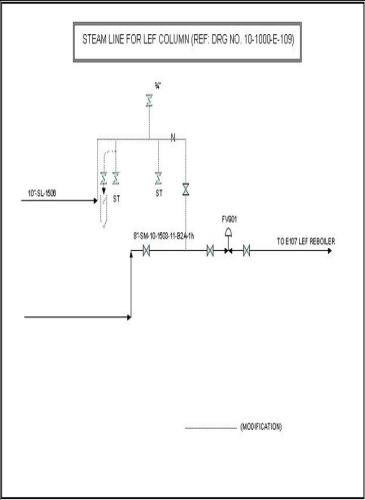
2.10 LIGHT ENDS FRACTIONATOR:
Refer P & ID No.10-1000-E-108, 109.
LEF COLUMN
Liquid from dryer D-102A/B and from feed gas separator-I and II (V-102 & V 103) are sent to Light Ends Fractionator, C-101. The column removes methane, ethane, a part of propane and most of carbon dioxide as overhead product.
LEF column is a 36.9 M tall column with 50 valve type trays. Carbon steel is used as material of construction for the column and trays, and stainless steel for the valves. The column is of varying diameter. It is 3.4 M O.D. at the stripping section and 2 M O.D. at the rectification section. In the stripping section trays with 2-pass are used whereas in the rectification section, trays with 1-pass are used.
The column is provided with temperature indicator on 6th, 36th and 48th trays i.e. TI-906, TI-904 & TI-902 respectively. It is provided with a differential pressure indicator DPI-901. Safety valve PSV - 901 A /B protects the column from overpressure.
The column operates at a top pressure of 28.3 Kg/CM2abs (presently, 28.5 Kg/CM2abs) and a bottom pressure of 29.30 Kg/CM2abs. The temperature at the 48th tray is controlled by a temperature controller; TIC-901 cascaded with FIC-901, which regulates the steam flow to Reboiler. The column operates at a top temperature of 2 OC (presently -2 to +1 OC) and a bottom temperature of 105.5 OC (presently 113-115 OC).
Column overhead vapors are condensed in LEF condenser, E-106 to about -19.2 OC (presently, -23 to –24 OC). LEF condenser is a partial condenser with the hydrocarbon vapors on the tube side being cooled by propane refrigerant on the shell side. The temperature of propane on the shell side is about -25 OC.
Column overhead vapors outlet temperature is indicated by TI-907. Temperature at outlet of condenser is indicated by TI-909. Column top pressure rides on the suction pressure of LEF 0/H expander compressor, which is controlled by PIC-801. PIC-801 operates on split range by either regulating the inlet vane of expander or bypass valve of expander.
Column overhead vapors condensed in LEF condenser flow to LEF Reflux drum, V-108. LEF Reflux drum is a 2.1 M O.D. and 5.1 M height carbon steel vessel fitted with a SS-304 wire mesh demister at the top. Uncondensed vapors from Reflux drum are sent to LEF 0/H expander compressor.
Liquid collected in the Reflux drum is refluxed back to the column on flow control (FIC-903) by light ends fractionator Reflux pumps. For quick stabilization of LEF column, reflux is established by taking feed gas separator-I liquid through a 2" line into the reflux drum.
Reflux drum is provided with a level controller, LIC-903.In case of high level due to excessive condensation in LEF condenser LIC-903 over rides LIC-1202 provided to control level in LEF condenser by regulating propane flow to LEF condenser through LV-1202. Presently, the above system is changed and LIC-903 is controlling the reflux flow only. Reflux drum is provided with high and low level alarms LAH -904 and LAL-905. At very high liquid level as sensed by LSHH-903, the expander compressor, EK-102 is tripped.
Light ends fractionator reflux pumps (P-101A/B) are centrifugal type pumps. They operate at a suction pressure of 28.2 Kg/CM2a and a discharge pressure of 33.6 Kg/ CM2a. They are designed for a normal flow of 34.7 M3 / Hr. and can develop a differential head of 102.9 M.
The reboil heat is provided by a kettle type Reboiler, E-107. Heating media is modified to LP steam (from MP) at kg/cm2g from cogeneration, which meets at u/s of FV-901. At present either MP or LP steam can be used as per the availability. Hydrocarbon on the shell side is heated by steam on the tube side. Vapor outlet temperature from Reboiler is indicated by TI-903. Steam flow to the Reboiler is controlled by flow controller FIC-901 and recorded by FR-901. This can be cascaded with TIC-901 which controls the 48th tray temperature of light ends fractionator. The 48th tray temperature is recorded by TR-901 and indicated by TI-902. In case of high pressure at column bottom (PSH - 901), steam flow to Reboiler is automatically cut off by closure of steam flow valve, FV-901.
Condensate from the Reboiler is collected in the condensate pot V-111. Condensate pot is 1 M O.D. and 2.15M height vessel of carbon steel construction. Condensate from condensate pot is removed on level control (LIC-901). Safety valve, PSV-902 is provided on the condensate pot to protect the vessel from over-pressurization due to reboiler tube failure. Liquid overflows a weir provided in the LEF reboiler from where it is withdrawn and sent to LPG column. LEF reboiler is provided with high and low level alarm, LAH-901 & LAL-902. Liquid to LPG column is sent on flow control (FIC-902) cascaded with L1C-902, which controls level in LEF reboiler. Flow to LPG column is recorded by FR-902.
2.11 LEF OVERHEAD EXPANDER-COMFRESSOR:
LEF overhead gases from LEF reflux drum are expanded in the expander section of LEF Overhead Expander Compressor (EK-102) from 27.5 Kg/CM2abs to 13.25 Kg/CM2 abs. As a result of expansion, the temperature of the gas drops down to about –44 OC.
Pressure at expander inlet is controlled by pressure controller PIC-801 which operates on split range either the expander inlet vane or expander bypass valve PV-801. A locally mounted HIC-801A is provided with auto manual selector switch AM-801A to either operate expander inlet vane locally or operate through PIC-801 depending upon the position of the selector switch. Locally mounted HIC-801B is provided with a local auto manual switch AM-801B and can be used to operate PV-801 locally. In Auto mode, PV-801 will be operated through PIC-801. Whether the inlet vane is operated through HIC-801A or through PIC-801, a speed override using SIC-801 is provided through a low selector LS-801.Control valve PV-801 can be operated by HIC-801B to pressurize the compressor section of expander compressor unit in order to give load and avoid over speed of the turbo expander.
High speed of turbo expander is indicated by SAH-802, very high speed of turbo expander as sensed by SAHH-801 trips EK-102 by closure of shut down valve, SDV-801. Interlock is provided to prevent the machine from starting unless the inlet nozzle opening is brought to minimum. Besides interlock is provided to prevent the machine from starting in case the bearing temperatures are low.
High and low pressure at expander suction is indicated by PAH-801 and PAL-802. Very high and very low pressure as sensed by PSHH-808 and PSLL-809 at expander suction trips the expander compressor unit. Very high differential pressure across expander suction strainer as sensed by dPSH-814 trips the expander compressor unit. Low pressure and temperature at expander outlet is indicated by PAL-810 and TAL-805. In case of very low pressure and temperature at expander outlet as sensed by PSLL-811 and TSLL-806 expander compressor will trip.
Refrigeration of gases at expander outlet is recovered in feed gas Chiller E-101 to cool down the feed gas stream. Gases from outlet of E-101 at about 5sC are routed to the compressor section of expander compressor through LEF 0/H Expander-compressor suction K.0. Drum V-105.
The suction K.O. drum V - 105 is 2.3 m O.D. and about 3.75 M height vertical vessel of charpy C.S. construction fitted with SS-304 demister at the top. The vessel is provided with high and low level alarms LAH-802 & LAL-803. Very high level in the vessel as sensed by LSHH-801 trips the expander compressor.
The pressure at compressor suction is controlled by pressure controller PIC-802 which by passes the excess pressure to Regeneration Gas Moisture separator through PV-802. The pressure at compressor suction would rise when the quantity of LEF 0/H gas exceeds the capacity of LEF 0/H expander compressor in which case the excess amount would bypass the expander through PV-801 and the same amount would have to be bypassed through PV-802 compressor to balance the load in the expander and compressor sections.
Compressed LEF overhead gases at 14.5 Kg/CM2a pressure are cooled in LEF 0/H Expander-Compressor after cooler E-123 to about 40 OC, and are routed to Regeneration Gas Heater, F-101 with excess pressure being bypassed to Regeneration Gas Moisture Separator. High temperature at compressor discharge is indicated by TAH-808. Very high temperature as sensed by TSHH-808A trips the expander compressor.
The compressor is protected against surging by anti-surge control loop, which maintains a minimum flow through the compressor by re-circulating a part of compressor discharge gas from outlet of E-123 to compressor suction through FV-802. Anti-surge control valves FV-802 is provided with volume bottle, which would supply additional air for operation of FV-802 in case of an instrument air failure. In case of high differential pressure across the compressor as sensed by dPSHH-815, the expander compressor unit will trip.
The Expander-Compressor machine is designed for a turndown of 50%. Lube oil, seal gas and cooling water are auxiliaries provided for the expander-compressor machines. The compressor discharge flow is supplemented with lean gas from compressor EK-101 A/B suction line through FV-801 to meet the following requirements.
a) LP lean gas requirement when LEF column is running on turndown.
b) To meet the turndown requirement of LEF 0/H expander
compressor when the LPG unit is running on turndown.
A bypass line 12" P-10-803-4-B1A, across the compressor is provided with tight shut off non-return valve and block valves to keep the LEF 0/H gases flowing in case LEF 0/H Expander compressor trips.
To prevent the mixing of cold process gas into lube oil and consequent freezing of lube oil and also to prevent lube oil from leaking into the expander casing, a stream of warm and dry seal gas is provided. During start-up, seal gas would come from dryer outlet through seal gas heater, E-125. Under normal operation seal gas will be supplied from the HP lean gas header. The change over is done manually.
The local control panel for the expander compressor machine is pressurized with instrument air. In case of loss of air pressure the expander-compressor machine gets automatically tripped. All process interlocks have been described for the machine except for the ones relating to mechanical parameters for which vendor documents should be referred to.
2.12 LPG COLUMN:
Refer P & ID No.10-1000-E-110.
Liquid from LEF reboiler is fed to LPG column at about 105.5 OC (113-115 OC presently) for separation of LPG and aromatic rich naphtha (ARN). LPG is withdrawn as column top product and ARN withdrawn as column bottom product, are sent to storage.
LPG column, C-102 is 2M O.D. and about 37.4M height, two-pass column with 54 valve trays. Carbon steel is used as the material of construction for the shell and trays and Stainless steel for the valves.
The column operates at a top pressure of 11.3 Kg/CM2abs (presently 11.7 Kg/CM2abs) and a temperature of 57.3 OC. The pressure at the bottom of the column is 12.0 Kg/CM2abs and the temp. is 155-156 OC. TI-1006, TI-l004 & TI-1002 are provided to indicate temperature at the 3rd, 19th and 35th trays respectively. DPI - 1001 gives the differential pressure across the column. Feed to the column can be sent to 14th, 18th or 22nd trays, depending upon the composition of the LEF bottom liquid. Presently 14th Tray is in use.
Vapors from the column top are condensed in LPG column condenser, E-108 and the condensed liquid is collected in LPG column reflux drum, V-109. The column pressure is controlled by split range pressure controller PIC - 1001, which operates PV_1001A on condenser bypass line and PV-1001B on 4" line from reflux drum to flare. LPG column condenser is flooded type. Column pressure is controlled by varying the area available for condensation in the condenser, which is achieved through the operation of PV-1001 A/B.
The column is protected by safety valves, PSV-1001 A/B against over pressurization. Column overhead vapor temperature is indicated by TI-1007.
LPG Column reflux drum is a 1.6 M O.D. and about 4.8 M long horizontal vessel of carbon steel construction. Liquid collected in the reflux drum is sent partly as reflux to the column on flow control (FIC-1002) and the balance is sent to LPG storage on level control of reflux drum (LIC-1002). The reflux drum is provided with high level and low level alarms LAH-1003 and LAL-1004.
As per recommendation during a safety audit for protection of V-109, the 2” nozzle on top of V-109 has been used to install a PSV-1003, discharge of which is connected to flare header, to take care in case of fire conditions.
LPG Column reflux pumps, P-102A / B (one operating plus one standby) are centrifugal pumps. They operate at a suction pressure of 11.3 Kg/CM2a and a discharge pressure of 20.4 Kg/CM2a. They are designed for a normal flow of 96.8 M3/Hr. and can develop a differential head of 176 M. Reflux flow to the column is recorded by FR-1002. LPG flow to storage is recorded by FR-1003 and the cumulative flow given by FQ-1003. Reflux temperature is indicated by TI-1008. To facilitate quick stabilization of LPG column during start up, reflux is established by taking LEF column bottom liquid through a 2" line into the reflux drum.
The reboil heat is supplied by LPG column reboiler, E- 109. Reboiler, E-109 is thermo-siphon type with carbon steel as the material of construction for the shell and tubes. Heat is supplied by medium pressure steam regulated by flow controller FIC-1001 which is cascaded with temperature controller TIC-1001, which controls the column temperature at the 35th tray. The column operates at a bottom temperature of 155 OC and a bottom pressure of 12 Kg/CM2abs. Condensate from the reboiler is collected in condensate pot V-112, from where it is routed to condensate header (medium pressure) on level control (LIC-1003). In case of high pressure at column bottom as sensed by PSH-1001 steam flow to the reboiler is cut off through solenoid valve action.
Aromatic Rich Naphtha is withdrawn from the bottom of the column on level control (LIC-1001) and sent to storage via Aromatic rich naphtha cooler, E-110 that cools the column bottom stream to 45 OC. In case of low temperature at reboiler outlet (TSLL-1002) the flow of ARN to storage is cut off by closure of LV-1001 through solenoid valve action. The column bottom is provided with high and low level alarms, LAH-1001 and LAL-1002. Low temperature at reboiler outlet is indicated by TAL-1003. ARN flow to storage is recorded by FR - 1004 and the cumulative flow to storage is given by FQ-1004.
2.13 PROPANE COLUMN:
Refer P & ID 10-1000-E-lll
A part of LPG product from upstream of FE-1003 is sent to Propane Column C-103 on flow control (FIC-1102) for fractionation to produce pure propane for use as refrigerant. LPG to propane column is fed on the 25th tray. Propane column is 1.2 M O.D. and about 25.5 M tall column with 35 one-pass valve trays. The material of construction for shell and trays is carbon steel and for the valves is stainless steel.
The column operates at a top temperature of 48.3 OC (42 OC at present). Vapors from the column top are condensed in a water-cooled condenser (Propane Column condenser, E-111) and the condensed liquid is collected in the reflux drum. The column top pressure is maintained at 16.3 Kg/CM2abs (14.5 Kg/CM2abs presently) by a split range pressure controller (PIC-1101) which either operates control valve PV-1101 A on cooling water line to the overhead condenser or operates PV-1101 B on line to flare from the reflux drum. PV-1101 A is provided with a minimum stop position to ensure flow of minimum amount of water to the overhead condenser. The column is protected against over pressurization by a safety valve PSV-1101. PSV-1101C has been installed later on, for sending the lighters to Fuel Gas Knock Out Drum (V-121), which was earlier, flared to maintain Column pressure during the Propane Column in operation.
Propane Column Reflux Drum, V-110 is 1.5 M O.D. and about 4.2M long horizontal vessel of carbon steel construction. The vessel is provided with high and low level alarms LAH-1103 & LAL-1104. Liquid collected in the reflux drum is partly sent as reflux to the column on flow control (FIC-1103) by propane Column Reflux Pumps, P-103 A/B and the rest is sent to LPG storage on level control of reflux drum (LIC-1102). For quick stabilization of propane column during start up reflux is established by taking LPG from column feed line through a 2" line to the reflux drum.
During a safety audit, it was recommended to install a PSV on the reflux drum to take care in case of fire conditions. Hence, from the 2” nozzle available on top of V-110, a 2” line has been laid and connected to PSV-1103, discharge of which joins the flare header.
Propane column reflux pumps, P-103A/B (one operating + one standby) are centrifugal pumps. The pump operates at a suction pressure of 14.2 Kg/CM2abs and a discharge pressure of 20.8 Kg/CM2abs. They are designed for a normal flow of 28.5 M3/Hr and can develop a head of 100 meters.
Propane is withdrawn as a side stream from the 6th tray and is sent on flow control (FIC-1104) either to storage or directly to the refrigeration system by Propane product Transfer pumps, P-104 A/B. The minimum flow requirement of the pump is met by flow controller FIC-1105 which operates FV-1105 to send the pump discharge as reflux to the column in case the product withdrawal rate is less than the minimum flow required for the pump.
Propane Product Transfer Pumps, P-104 A/B are centrifugal
pumps (one operating and one standby). The pumps operate at
a suction pressure of 17.4 Kg/CM2abs and a discharge pressure of 19.6 Kg/CM2abs. The pumps are designed for a normal flow of 2.75 M3/Hr and can develop a differential head of 48.4 meters.
The reboil heat is supplied by Propane column Reboiler, E-112. The reboiler is of thermo-siphon type. Carbon steel is used as the material of construction for shell and tubes. Heat is supplied by low pressure steam regulated by flow controller FIC-1101 which is cascaded with temp. controller, TIC-1101, which controls the column temperature at the 33rd tray. The column at the 33rd tray is maintained at 66.8 OC. The column operates at a bottom temperature of 79.25 OC and a pressure of 16.6 Kg/CM2abs as design or 69.0 OC at 13.5 kg/CM2G presently.
In case of high pressure at the column bottom as sensed by PSH-1101, steam flow to the reboiler is cut off by closure of FV-1101 through solenoid valve action. Temperature indicators are provided for the 3rd, 27th and 33rd trays (TI-1106, TI-1104 and TI-1102 respectively). The column is provided with high and low level alarms LAH-1101 and LAL-1102. Condensate from the reboiler is collected in propane Column Condensate Pot V-113 from where it is routed to condensate header (low pressure on level control, LIC-1103). Propane Column bottom product is sent to LPG storage on level control (LIC-1101) after cooling it to 45 OC in Propane Column Bottom Cooler, E-113. In case of high temperature at the outlet of E-113 as sensed by TSHH-1101 the column bottom flow is stopped by closure of LV-ll01.
Lighter fractions can be diverted to fuel gas KOD through the modified line having the pressure control PV-1101C.
2.14 REFRIGERATION SYSTEM:
Refer P & ID No. 10-1000-E-112.
Refrigeration for achieving low temperature is provided using propane as the refrigerant. Propane refrigerant of the following composition is used.
Ethane 0.70 mole%
Propane 99.05 mole%
i-Butane 0.25 mole %
Propane Compressor K-105 is a two stage motor driven centrifugal compressor. For details of the compressor, motor and auxiliaries refer to the vendor's manual.
Refrigerant gas to the various stages of the compressor comes from two suction drums operating at different levels of temperature and pressure. These suction drums are vertical vessels with demister fitted at the top. Vessels are provided with liquid level gauges and level switches.
The 1st stage of the compressor operates at suction pressure of 1.85 Kg/CM2a. High pressure at the compressor suction is indicated by PAH-1205. In case of suction pressure going very low (PSLL-1204) the compressor is tripped. Propane vapors are compressed in the 1st stage to a pressure of 6 Kg/CM2abs. To these vapors, the vapors from propane 2nd stage suction drum, V-119 join and are compressed to a pressure of 13 Kg/CM2a in the 2nd stage and the discharge temperature rises to about 71 OC. The compressor trips in case of very high pressure or very high temperature at outlet (PAHH-1202 & TAHH-1202). Vapors from compressor discharge are condensed in Propane Refrigeration Condenser, E-118 A/B and the condensed liquid is sent to Propane Refrigerant Accumulator, V-117. E-118 A/B are flooded type condensers. The pressure at the compressor discharge is controlled by pressure controller PIC-1201 which operates hot vapor bypass valve, PV-1201 and varies the tube bundle submergence in E-118 A/B. PIC-1201 can be cascaded to compressor suction pressure controller, PIC-1203.
Propane Refrigerant accumulator is 1.6 M O.D. and about 4.5 long horizontal vessel of carbon steel construction. The vessel is provided with high & low level alarms LAH-1201 and LAL-1202.Liquid propane at about 14 Kg/CM2abs pressure and 40 OC temperature is withdrawn from the accumulator on level control LIC-1201 and is expanded to a pressure of 6.19 Kg/CM2abs in Propane Refrigeration Economizer, V-118. As a result of expansion, the temperature of liquid propane drops to 8 OC. Propane Refrigeration Economizer, V - 118 is 1.6 M O.D. and about 5.6 M height vertical vessel of carbon steel construction fitted with a SS-304 demister pad at the top. It is provided with a level transmitter and high and low liquid level alarms. Vapors from economizer are routed to the 2nd stage of the compressor through Propane 2nd stage suction Drum, V-119. HIC-1202 is provided to maintain compressor suction pressure during start up of the system.
Liquid Propane from the economizer at 6.19 Kg/CM2a pressure and 8 OC temperature is expanded further to a pressure of 2 Kg/CM2a (1.85 Kg/CM2a) in a light ends fractionator condenser, E-106. As a result of this expansion the temperature of propane falls down to -25 OC. Level in LEF condenser is controller by LIC-1202 which regulates the flow of propane to LEF condenser by operating LV-1202. Presently this LIC-903 is directly controlling the Reflux Drum level. High level in LEF condenser is indicated by LAH-1210.
Propane vapor from LEF condenser is routed to the 1st stage of the compressor through propane 1st Stage Suction Drum, V-120. HIC-1203 is provided to control the suction pressure of the compressor during start-up.
To meet the minimum flow requirement of the compressor a part of the vapors from compressor discharge are recycled to compressor 1st stage and 2nd stage suction on flow control. For this purpose FIC-1201 and FIC-1202 operate control valves FV-1201 and FV-1202 respectively. FV-1201 and 1202 open whenever the compressor suction flow tends to fall. Compressor 2nd stage minimum flow controller FIC - 1201 can be cascaded to minimum flow computing relay. The relay automatically computes the set point of the minimum flow controller by calculating the difference between the compressor 2nd stage minimum flow requirement and the vapor flow from the compressor 1st stage. This system saves the compressor power requirement during turndown conditions.
To ensure no super heating in the minimum flow vapor lines, liquid refrigerant as quench is sprayed in it through quench nozzle. Nozzle downstream vapor temperature is maintained by TRC-1201 & 1202 that regulates the amount of quench spray through TV-1201 & 1202. An additional Quench has also been installed in the propane line from V-118 standpipe bottom to down stream of TV-1202.
Propane 2nd stage suction drum, V-119 is 1.6 M O.D. and about 3.45 M height vertical vessel of carbon steel construction fitted with a SS-304 demister pad at the top. At the bottom of the vessel is stubbed 2nd stage Propane Vaporizer, E-119. The design of the vaporizer is such that propane liquid in V-119 can be vaporized upto low liquid level height (i.e. 150 MM from bottom TL). The heat of vaporization is given by a slipstream taken from compressor discharge, which after passing through E-119 joins the inlet to Propane refrigerant Economizer (V-118). The vessel is provided with high-level alarm LAH-1207. In case of very high level in the vessel (LAHH-1206) the compressor trips.
Propane 1st Stage suction Drum, V-120 is 2.6 M O.D. and about 4.45 M height vertical vessel of charpy carbon steel construction fitted with a SS-304 demister at the top. At the bottom of the vessel is stubbed 1st stage Propane vaporizer, E-l20. The design of the vaporizer is such that propane liquid in V-120 can be vaporized upto a low liquid level height (i.e.150 MM from bottom TL). The heat of vaporization is given by a slipstream taken from compressor discharge, which after passing through E-120 joins the inlet to Propane Refrigeration Economizer, V-118. The vessel is provided with high level alarm, LAH-1209. In case of very high level in the vessel (LAHH-1208), the compressor trips.
In case of compressor trip HCV-1201, 1202, 1203, TV-1201 & 1202 are closed by solenoid valve action to avoid pressurization at the downstream of these control valves and compressor suction lines. The shutdown of these valves is necessary to avoid unnecessary venting of Propane in bringing down the compressor suction pressure required for starting up the compressor after a shut down.
The initial filling of the system with propane can be done by taking propane directly from propane column or from storage. The system is thoroughly dried before taking propane by taking fuel gas through line 6" FG-10-1403-1-A1A and passing it through the gas dryer and heater and loading it refrigeration section through dry out line 6 "P-10-406-9-D1A. A new mass flow meter (Endress Hauser make) has been installed in the existing 2” propane make up line, for local measurement of propane consumption.
Propane Refrigerant Transfer Pumps P-107 A/B is used to transfer propane hold up in the system to Propane storage. These pumps (one operating and one standby) are centrifugal pumps. The pumps operate at a suction pressure of 2.2 Kg/CM2abs and a discharge pressure of 19.7 Kg/CM2abs. They are designed for a maximum flow of 5 M3/Hr and can develop a differential head of 336 meters.
2.15 FLARE AND BLOW DOWN SYSTEM:
Refer P & ID 10-1000-E-113 A & B.
2.15.1 FLARE SYSTEM:
The discharge from various safety valves, control valves and pump casing vents in the unit are collected in the flare header, which flow to flare K.O. Drum, V-122. Flare K.O drum is 4.5 M O.D. and about 11 M long horizontal vessel of carbon steel construction. Flare gases from Knockout drum outlet are routed through a 36" line to 48" Flare header of Hazira Plant. Flare K.O. Drum is provided with a high level alarm LAH-1302. Flare header is provided with a fuel gas purge connection at the dead end of the header in LPG unit. The flow of fuel gas is regulated by restriction orifice, RO-1301.
Excessive flaring of hot gases is to be followed by higher purge rates of fuel gas to avoid flare header developing vacuum. Higher fuel gas purge rates are obtained through HCV-1301 operated by HIC-1301.
2.15.2 BLOW DOWN SYSTEM:
Closed blow down system is provided to collect liquid contents of pipelines, column, vessels and other equipments. This blow down is routed through the blow down header to Blow down Drum, V-123. Blow down Drum is 2.4 M O.D. and about 4.55 M height vertical vessel of SS-304 construction. The vessel is provided with a high level alarm, LAH-1301. Liquid collected in the Blow down drum is vaporized in Blow down Vaporizer, E-121. Heat for vaporization is supplied by low pressure steam on the shell side of the vaporizer. Stainless steel is used for the tubes and carbon steel for the shell of the vaporizer. Hydrocarbons vaporized by the Blow down Vaporizer are routed to the unit flare header. The Blow down header is given a continuous fuel gas purge through restriction orifice, RO-1302 at the dead and of the header.
2.16 UTILITY SYSTEM:
Refer P & ID's Nos. 10-1000-E-114, 115 & 10-20-00-E-211.
The utility system consists of instrument air, plant air, inert gas, fuel gas, Methanol, Cooling Water, steam (LP & MP) condensate (LP & MP) and service water.
2.16.1 INSTRUMENT AIR:
A 3" instrument air header supplies instrument air to the unit at a pressure of 7 Kg / CM2abs. A block valve with a blind is provided at the battery limit. A pressure gauge PG-1404 indicates the pressure of instrument air to the unit. The various instrument air tappings are taken off this header. The header is provided with a low pressure alarm PAL-1404.
An instrument air receiver (V - 124) is provided to supply instrument air to gas receiving and plant bypass instruments to ensure supply of gas to consumers in case of instrument air failure. The vessel is 2.3 M O.D. and about 5.75 M height vertical vessel of carbon steel construction. It is operated at the pressure of 7 Kg/CM2abs and has a hold up capacity of 45 minutes. The vessel is provided with a low pressure alarm, PAL-1406.
2.16.2 PLANT AIR:
Plant air is supplied to the unit at various hose stations through a 2" header at a pressure of 7.0 Kg/CM2abs. The header is provided with a block valve and blind at the battery limit followed by a pressure gauge, PG-1406.
2.16.3 INERT GAS
Inert gas is supplied to the unit at a pressure of 6.5 Kg/CM2abs. Inert gas is produced by combustion of fuel gas in an inert gas generator. This is coupled with a drying unit. Inert gas of the following specification shall be supplied to the plant.
i) Dew Point @ 8.0 Kg/CM2a -40 (-50 Max.)OC
ii) Temperature at B/L, 40 (50 Max.) OC Nor.
iii) COMPOSITION:
Component Volume, %
H2 0.1 (Max)
02 0.5 (Max)
CO 0.1 (Max)
C02 & N2 Balance
Inert gas is made available at the various hose stations. It is also used for purging of distance piece of compressors and for purging of the cold box for feed gas Chiller, E-101.
2.16.4 COOLING WATER:
Cooling water to LPG unit is supplied at a pressure of 5 Kg/CM2a and at a temperature of 33 OC to various coders and condensers. Outlet water of exchangers E-102A/B, E-111, E-118A/B and E-123 at 37 OC is reused in exchanger E-103A/B, E-104, E-110 & E-113. Hot water from exchangers is returned to the cooling tower through the cooling water return header. Cooling water supply and return headers are provided with motor operated valves at the battery limit. Cooling water supply header is provided with a pressure indicator, PI-1501 a flow indicator FI-1501 and a low pressure alarm PAL-1501.
2.16.5 LP STEAM AND CONDENSATE:
a) LP steam is supplied to LPG unit at a pressure of 3.2 Kg/CM2 abs and at a temperature of 126 OC by reducing the pressure of MP steam (through PV-402B) followed by de-superheating. This route is isolated at present. LP steam generated by f1ashing of MP condensate in flash drum 20-V-202 also joins the LP Steam (V-202 is not in use at present). LP Steam from Cogen at 7 Kg/CM2a also joins this header after dropping pressure across PV-402A.
b) LP steam of cogeneration at 7 kg/cm2g is also used in LEF Reboiler (E-107) for reboil heat duty.
LP Steam (3.2 kg/cm2) is being used in various exchangers, at hose stations and for heat tracing. The header is provided with a flow indicator/integrator, FI-1502/FQ-1502, a pressure indicator PI-1503 and a low pressure alarm, PAL 1503. Low pressure condensate is collected in an atmospheric flash drum and then pumped out to offsites on level control of LP condensate flash drum, 20-V-201 through P-217 A/B.
2.16.6 MP STEAM AND CONDENSATE:
MP steam is supplied to LPG unit at a pressure of 18 Kg/CM2a and at a temp. of 200 OC from MP boiler. It is used in LPG REBOILER (E-109). Medium pressure condensate is flashed in MP condensate flash drum (20 V-202), which is at present isolated. V-213 has been installed & MP condensate is lined up presently to this vessel. Low pressure steam generated as a result of flashing joins the LP Steam Header from Co-generation to LPG unit. LP condensate from MP condensate flash drum is sent to offsites on vessel level control or, the same can be sent to LP condensate pot (20-V-201) through a 2" line.
2.16.7 SERVICE WATER:
Service Water is supplied to LPG unit from offsite area at a pressure of 5 Kg/CM2abs through a 2" header. Service water is made available at various hose stations.
2.16.8 FUEL GAS SYSTEM:
Fuel gas system is designed to cater to the fuel gas requirement of regeneration gas heater, boilers, flare, and inert gas plant and for purging of flare and blow down headers. The fuel gas requirement is met by low pressure lean gas available from regeneration gas moisture separator outlet. During plant start up and shutdown fuel gas is taken from the feed gas header through line 3"P-10-101-2-DIA. In addition fuel gas make up is provided in the off sites FG header from the 30" HBJ pipeline and HP lean gas line after pressure let down.
Fuel gas tapped from feed gas header is heated to 60 OC in pipeline Fuel Gas Heater, E-124 to avoid hydrate formation during pressure letdown. The heater is electrically heated. Temperature of fuel gas at heater outlet is controlled by temperature controller TIC-1403 which varies the current in the heater coil through a thyristor control arrangement. In case of high fuel gas temperature at heater outlet as sensed by TSHH-1401 the electrical supply to the heater is automatically cut off. The heater coil is provided with high skin temperature switch TSHH-1402 which cuts off electrical supply to heater in case of high coil skin temperature. Fuel gas from heater outlet joins fuel gas from LP lean gas header coming from Regeneration Gas Moisture Separator Outlet and is routed to fuel gas K.O. Drum after reducing the pressure to 4.5 Kg/CM2abs (presently 4.1 Kg/CM2abs).
Fuel gas K.O. Drum V-121 is 1.6M O.D. and 3.45M tall vertical vessel of carbon steel construction with SS-304 demister fitted at the top. The vessel is provided with steam heated coils to vaporize any condensate separated in KOD. The outlet from K.O. drum forms the fuel gas header which supplies fuel gas for internal consumption in LPG unit and various other units of Hazira Plant. A 2" fuel gas line is taken from fuel gas K.O. drum bottom to flare header to blow down any liquid hold up, if required. Fuel gas header pressure is maintained at 4.5 Kg/CM2abs (presently 4.1 Kg/CM2abs) by pressure controller PIC-1401 which operates on split range PV-1401A and PV-1401B. In case of header pressure going beyond 5.5 Kg/CM2abs the excess gas is flared through PV-1402, which is operated by PIC-1402.
Fuel gas header is provided with high and low pressure and low temperature alarms PAH-1402, PAL-1403 & TAL-1404 respectively. In case of very high pressure as sensed by PSHH-1401 fuel gas flow to fuel gas K.O. Drum is isolated by closing of control valves PV-1401 A/B, shutdown valve SDV-1401. Power supply to fuel gas heater E-124 is also cut off.
Fuel gas flow from LPG unit to other units of Hazira Plant is indicated by FI-1401 and the cumulative flow given by FQ-1401. A 1" line is tapped from outlet of Fuel Gas Heater to provide fuel gas for regeneration of dryer beds during plant start up when LEF 0/H gases are not available.
2.16.9 METHANOL SYSTEM:
Methanol is used as antifreeze agent whenever ice or hydrate formation is likely to take place. Methanol requirement arises mainly during plant start up and during times when there is ingress of moisture into the system. Methanol dissolves ice/hydrate and comes out of the system along with the heavies.
Methanol is unloaded into methanol drum 20-V-212 from road tankers. Methanol drum is 2.5M 0.D. and 5M long underground vessel located in the off sites storage area. The vessel is blanketed with fuel gas. Pressure of 1.2 Kg/CM2abs is maintained by pressure regulator 20-PCV-1102. A pressure cum vacuum relief valve 20-PVRV-1102 is provided on the vessel. The vessel is also provided with a level indicator 20 LI-1101.
Methanol from methanol drum is transferred to Methanol pot 20-V-207 located within the LPG unit by methanol transfer pump 20-P-211. Methanol transfer pump 20-P-211 is a submersible centrifugal vertical pump. The pump is submerged in the methanol drum. The pump operates at a suction pressure of 1.2 Kg/CM2abs and a discharge pressure of 3.2 Kg/CM2abs. The pump is rated for 10 M3 and can develop a differential head of 26.7 M. In case of low level in methanol drum as sensed by LSL-1102, the pump is tripped.
Methanol pot (V-207) is 2M O.D. and 4M height vertical vessel of carbon steel construction. The vessel is blanketed with fuel gas at a pressure of 1.2 Kg/CM2abs through pressure regulator, PCV-1101. The vessel is provided with a pressure cum vacuum relief valve, PVRV-1101. The vessel is also provided with a level gauge and high level alarm, LAH-1101.Methanol from the methanol pot is pumped to the methanol supply header of LPG plant by methanol injection pumps 20-P-212 A/B.
The injection pumps (one operating plus one stand by) are motor driver reciprocating pumps operating at a suction pressure of 1.2 Kg/CM2abs. The supply header pressure is maintained by PIC-1101, which bypasses the excess pressure back to the condensate pot. Provision exists in the pumps for varying the stroke length from 0-100%. Methanol from the supply header is injected at desired locations through out the unit.
2.16.10 FIRE WATER DELUGE SYSTEM:
An automatic deluge Valve assembly for firewater distribution has been installed in LPG plant. The size of the deluge valve is 4” with a rated flow of 51 to 80 m3/hr and a working pressure of 7 to 10.5 kg/cm2g. The deluge valve is provided with solenoid operated air release valve for remote operation. It is actuated through pressure switch in Instrument air line, which will in turn get actuated on pressure going low in instrument air line. Low air pressure alarm is set at 1.7 kg/cm2 while for fire it is set at 0.7 kg/cm2. When fire occurs and deluge valve opens, water operated alarm gong is sounded.
An 1.5” distribution pipe is provided for P-101A/B, P-102A/B, and P-103A/B with 2 nos. of spray nozzles (0.5”) provided for each pump, and 1 spray nozzle fitted with quartzoid bulb detector for each pump. An integral test and drain manifold is fitted on the deluge valve for testing and draining.
2.16.11 SAFETY/ EYE WASH SHOWERS:
In addition to the safety showers already existing at the North B/L (near V-207), two more eye wash showers have been installed at both ends of the LPG plant. For this purpose, a new 2” GI line has been laid from the North B/L and the showers put near V-214 and near F-101.
2.17 CONTROL ROOM:
The operation of the plant is controlled from a centralized control room utilizing Digital Distributed Control system (DIDC). Apart from the local control panels for operation and control of various equipments and their auxiliaries, LPG unit is being controlled and monitored by the LPG unit operator’s console station of DIDC system. The LPG control station is housed in the main control room building along with utilities and off sites control station. Each control station is having three VDU’s and a printer.
In the event of LPG operator console failure the controls of LPG unit parameter are transferred to utility & offsite operation console. In the event of total failure of consoles the control action of controllers are available from the SLPC’s provided in the rear panel. All hardwired alarms are displayed in the annunciator located above the cabinet housing the SLPC’s. PSV settings are listed in page no. 24 & 25 of graphics in the control panel.
EMERGENCY PROCEDURE:
IN CASE OF POWER FAILURE:
1) All running equipment like motors and compressors will trip.
Gas to consumers will be available through plant bypass. If the upstream sweetening units are not affected, maintain the gas supply to consumers.
If the upstream units gas sweetening units are also affected, stop the supply of gas to consumers.
2) Close 10-PV-103, PV-11, PV-12, and PV-13. Isolate consumer lines at Gas Terminal also.
3) If furnace is in on position, stop the fuel gas to burners. Isolate the 3” ball valves.
4) Isolate TV-1201, 1202 and additional quench of the refrigeration system.
5) Steam to all reboilers to be cut off.
6) Divert propane to LPG sphere if propane column is in operation.
7) Isolate the Hydrocarbon condensate supply from DPD units.
8) Watch pressures, temperatures, levels in various equipments. Release the excess pressure to flare header and excess levels to blow down header to maintain conditions under control.
9) In case the LEF column pressure tends to increase, depressurize at a slow rate. Do not route the gas through F-101.
10) Maintain the seal gas to expanders, change over seal gas supply from lean gas header to feed gas header, if required.
11) Close LV-1201, 1202 and FV-1201. Isolate K-105 suction and discharge valves.
12) Keep vigil in the plant.
SECTION-3
OPERATING PROCEDURES
3.1 INTRODUCTION:
In this section under operating procedures start-up, shut down and normal operating procedures are discussed. Emergency procedures are also covered in this section. The most critical periods in operation are those of start-up and shut down. It is then, that the hazardous possibilities of fire and explosions are the greatest.
One of the hazards most frequently encountered during start-up and shut down of unit is accidental mixing of air and hydrocarbons. Other hazards primarily associated with start-up/shut down are pressure, vacuum, thermal and mechanical shocks. These can result in fires, explosions, destructive pressure surges and other damages to the unit as well as injury to personnel.
It is essential that the operation crew realize the potential hazards involved in the start-up and shut down operations and eliminate them by diligently following the procedures outlined below.
3.2 START UP:
3.2.1 PREPARATION:
Prior to actual commissioning of the unit, it should be established that all preparatory works have been successfully completed and all equipments are ready to function. To ensure that:
a) The blinds in product lines at battery limit valves have been reversed/removed with proper entry in the blind register which will also give the correct position of all blinds during start-up/shut down.
b) All vessels, piping and equipment have been flushed and dried, leak tested and ready for service. Cold box housing has been filled with insulation and a positive pressure of inert gas is maintained.
c) All machineries such as motors, pumps, compressors etc., have undergone functional tests successfully. All instruments have been calibrated and checked & controls are on manual.
d) All instruments have been calibrated and checked and controls are on manual.
e) All safety valves are in position after setting and testing. Isolating valves will be left in lock open position with blinds removed. Spare valves, if any, should be kept isolated.
f) Refractory drying of heater is completed.
g) Column packings including molecular sieves in dryers are
charged & filter medias are installed. There should be adequate inventory of methanol.
h) Utility headers have been commissioned.
i) Fire hydrant system is energized and ready.
j) OWS and sewer systems are ready.
k) Flare and closed blow down systems are purged and are in operable condition.
l) All pre-commissioning activities are completed.
m) The related units are informed of plant start-up plan and good communication is established with them.
n) Plant electrical systems are ready. Instrument power is available for main and local control panels. Plant communication systems are ready.
3.2.2 SUMMARY:
The summary of start-up procedure is as follows.
The entire system is purged with inert gas to free the system of air to less than 0.5% oxygen. Blow down system is lined up with flare and the flare header is connected to the flare tower. After displacing air, fuel gas/feed gas is taken for system drying.
Pressurizing of the system will be done stepwise with feed
gas/fuel gas and at each step of pressure rise leak checking will be carried out. Final leak check will be with feed gas pressure.
Molecular sieve/drier vessels shall be regenerated, cooled and kept ready for service. System starting from feed gas filters, chill down section and Light Ends Fractionator shall be dried by feed gas through molecular sieve dryers. Refrigerant system shall be dried using fuel gas after passing through molecular sieve dryers and regeneration gas heater. Refrigerant propane shall be taken into the refrigeration system as vapor and the system pressurized. Subsequently liquid propane shall be charged and refrigeration cycle shall be started achieving desired temperature levels. Later gas flow at about 40% of design shall be established through the unit. Process gas temperature will fall and condensed liquid will appear in Separator - I and II. This liquid will be routed to Light Ends Fractionator.
Light Ends Fractionator shall be started with light ends joining the lean gas header through Residue Gas Compressor and bottoms flowing to LPG columns. The column shall operate at total reflux.
LPG column shall be started and established with overhead product LPG going to storage and bottom product Aromatic Rich Naphtha going to storage.
Condensate handling system shall be commissioned by taking feed liquid from Dew Point Depression Unit. Plant through put shall then be raised to 100% of design.
Propane column shall be started taking LPG from LPG column for fractionation. Overhead product, propane shall be routed to propane storage and the column bottom product shall be routed to LPG storage.
The various steps leading to a safe and smooth start-up of the LPG unit is as follows:
a) Purging the unit with inert gas.
b) Commissioning LPG flare header/blow down system.
c) Commissioning of Fuel gas system.
d) Commissioning of methanol system.
e) Regeneration of molecular sieve.
f) System drying with feed gas.
g) Drying of refrigeration system.
h) Charging of refrigerant and establishing refrigeration cycle
i) Establishing feed gas flow taking expander compressor, EK-101 and lean gas
compressor in line.
j) Commissioning of Propane Column.
k) Normalizing the unit.
START-UP PROCEDURES:
A) PURGING THE UNIT:
The entire system including fuel gas, flare, blow down and methanol system is to be freed of air to less than 0.5% oxygen before taking in fuel gas or feed gas for drying. For purging the plant with inert gas, nitrogen produced by the inert gas generator and supplied to the unit through inert gas header be used. Inert gas connections shall be done at various utility connection points, drain and vents of equipment and piping to purge the system. For purging, the unit may be divided into various systems. Purging is accomplished by depressurizing to 0.5 Kg/CM2G. When pressurizing system for purging, care must be taken so as not to exceed the design pressure of the system under purge. After purging, the system shall be kept pressurized under a positive pressure to avoid ingress of air.
B) COMMISSIONING OF FLARE HEADER AND BLOW DOWN SYSTEM:
After the system has been inertised and oxygen level ensured to be less than 0.5% in flare header and blow down system, the 36" flare header from flare KO drum is integrated with the 48" flare header of Hazira Plant. Ensure the 8" valve on the inlet line to Blow down Drum is opened. Commission steam to the Blow Down vaporizer and check that steam trap on condensate line from the vaporizer is working properly.
Care must be taken to equalize the pressure in the flare header for Hazira Plant before the 36" valve on flare KO drum (V-122) outlet is opened. Establish the fuel gas purge to flare and blow down headers after commissioning fuel gas system. HCV-1301 is kept lined up but is left in closed position.
C) COMMISSIONING OF FUEL GAS SYSTEM:
Fuel gas for starting up the unit is taken through a 3" line from the feed gas line. Once the unit is on stream, LEF overhead gas shall be used to meet the fuel gas requirement of LPG unit. E-124 is not used at present.
For commissioning of fuel gas system, proceed as follows:
- The system is already inertised and is under a slight positive pressure of nitrogen.
- Line up the system as follows:
![]() Feed Gas line------------------ >3" tapping to E-124------------------ >V-12l-------
Feed Gas line------------------ >3" tapping to E-124------------------ >V-12l-------
![]() Fuel Gas header 10"FG-10-1401-1-A1A <--------------------------------------------
Fuel Gas header 10"FG-10-1401-1-A1A <--------------------------------------------
Flare header <----------- PV-1402 <-------
- Check all instrument and safety valves are in line.
- Check fuel gas to all consumers is isolated.
- Check steam tracing on the fuel gas line is commissioned
- Commission steam to fuel gas K.O, Drum.
- Keep PV-1401B in closed position.
- Set PIC-1402 at 5.5 Kg/CM2abs on Auto.
- Slowly open isolation valve d/s of SDV-1401 and pressurize up to PV-1401 B till the feed gas 1ine pressure is achieved.
- Switch power to fuel gas heater and set TIC-1403 to control at 60 OC.
- Open PV-140lB on manual and pressurize fuel gas KO drum and fuel gas header, up to 4.5 Kg/CM2abs.
- Take PIC-1401 on Auto to control at 4.5 Kg/CM2abs.
Establish fuel gas purge to flare and Blow down header.
- Line up PV-1401A when LEF overhead gas is available to cater for the fuel requirement of LPG unit.
- Line up fuel gas to 4" header leading to other units of the Plant when it is ready to receive fuel gas.
D) COMMISSIONING OF METHANOL SYSTEM:
Inertising of methanol system is followed by introduction of fuel gas into Methanol Pot, V-207 for blanketing. Fuel gas pressure of 1.2 Kg/CM2 abs is maintained in the methanol pot. Methanol is then received into the methanol pot from offsite area through a 3" line. Methanol injection pump is then lined up and the flow is established through the recirculation line maintaining a backpressure of 69 Kg/CM2abs with PIC-1101. Before starting the methanol injection pumps, it should be ensured that all isolation valves at methanol injection points are closed.
E) REGENERATION OF MOLECULAR SIEVE:
LEF overhead gas is used for regeneration of molecular sieve during normal operation. During start-up of the LPG unit when LEF overhead gas is not available, regeneration of molecular sieve is carried out with feed gas. Regeneration of molecular sieve of gas and liquid dryers for first start-up with feed gas is described first. This is followed by regeneration of molecular sieves of gas and liquid dryers with LEF 0/H gases during normal operation.
FEED GAS DRYER (REGENERATION FOR FIRST STARTUP):
Line up of the system is as follows:
![]() PV-804B TO FLARE
PV-804B TO FLARE
![]()
![]() Line1"-P-10-1401-2-DIA---------->V-106----------------->
Line1"-P-10-1401-2-DIA---------->V-106----------------->
![]() ------------------>PV-804A
------------------>PV-804A
![]() <-------F-101<--------V-107<---------E-105<----------K104 A or B
<-------F-101<--------V-107<---------E-105<----------K104 A or B
![]() -- -----D-101A----- ----->E-104----------- -------->V-106
-- -----D-101A----- ----->E-104----------- -------->V-106
- Check instruments and safety valves are in line.
- Isolate moisture analyzer, as it is not designed for hot gas.
- Commission cooling water to E-104 & E-105.
- Set PIC-804 at 11 Kg/CM2abs on Auto.
- Introduce feed gas by opening 1" valve on line 1"P-10- 1401-2DIA and pressurize the system to 11 Kg/CM2abs.
- Keep FV-401 fully open on manual.
- Keep HCV-402 lined up to gas dryer for regeneration.
- Start one residue gas compressor and run it at full load. As the compressor is started the compressor suction pressure will start falling. Maintain suction pressure of the compressor at 11 Kg/CM2a by making up with feed gas. Compressor discharge pressure will be higher than the suction pressure by an amount equal to the pressure drop of the regeneration loop. However compressor discharge pressure should not exceed 18 Kg/CM2a i.e. set point for safety valve at heater outlet.
- Fire the heater and raise the temperature at heater outlet at a uniform rate to 265 OC. Heater firing rate should be increased in accordance with the recommendations of the refractory manufacturer (50 OC/hr max).
- The heating cycle for the dryer shall be of a longer duration than specified as regeneration gas flow obtained from one residue gas compressor will be less than the normal regeneration flow of 24,000 Kg/Hr. Continue the heating cycle till dryer outlet temperature is 250-260 OC. Maintain at this temperature for 1 hour.
- Cut down on heater firing to bring down the heater stack temperature to 200 OC at the rate of 50 OC/Hr. Shut down the heater. Divert the gas flow through heater bypass line to start cooling cycle till the bed temperature is brought down to 45 OC.
Carry out regeneration of Gas dryer D-101B in similar way.
LIQUID DRYERS (REGENERATION FOR FIRST START UP):
Line up of the system is as follows:
![]() PV-804 B-----> Flare
PV-804 B-----> Flare
![]() Line 1"P-10-1401-2-DIA----------------->V-106--------------->K-104A or B
Line 1"P-10-1401-2-DIA----------------->V-106--------------->K-104A or B
![]() E-104 --------------------------------
E-104 --------------------------------
![]()
![]() Thro’HCV-401 PV-804A
Thro’HCV-401 PV-804A
D-102A<—-------------F-101<------------V-107<---------------------E-105
- Check all instruments and safety valves are in line.
- Isolate moisture analyzer, as it is not designed for hot gas. .
- Check cooling water is commissioned to E-104 and E-105.
- Set P1C-804 at 11 Kg/CM2abs on Auto.
- Pressurize the regeneration circuit to 11 Kg/CM2a by introducing feed gas from line 1"P-l0-1401-2DPA.
- Keep HCV-401 fully open and FV-402 fully closed.
- Start one residue gas compressor at 50% loading. As the compressor is started the suction pressure will fall down. Maintain the suction pressure at 11 Kg/CM2a by making up the pressure with feed gas. At 50% loading, the compressor discharge flow will be approximately 9315 Kg/Hr. It is important to run the residue gas compressor at minimum 50% loading to achieve enough flow through the heater so as not actuate the low flow trip.
- Open FV-402 slowly and establish a flow of 6000 Kg/Hr through liquid dryer D-102A by throttling HCV-401. Take FIC-402 on Auto set at a flow of 6000 Kg/Hr.
- Fire the heater and bring up the temperature at heater outlet to 265 OC. Heater firing rate should be increased in accordance with the recommendations of the refractory manufacturer.
- Continue heating cycle till dryer outlet temperature is 250-260 OC. Maintain at this temperature for 1 hour.
- Cut down on heater -firing to bring down the stack temperature to 200 OC at the rate of 50 OC/Hr. Continue the cooling cycle maintaining the gas flow through the dryer with heater bypassed.
- Cool the dryer bed to 45 OC.
- Carryout regeneration of dryer bed D-102B in similar way.
FEED GAS DRYER (REGENERATION DURING NORMAL OPERATION):
Regeneration of molecular sieve for feed gas dryer becomes necessary when the dryer bed gets exhausted. Regeneration of the molecular sieve is carried out by heating the LEF 0/H gases upto 270 OC in regeneration gas heater and passing it through the dryer bed to vaporize the water molecules embedded in the molecular sieve. Schedule for drying and regeneration is described in Section 2.3.2. However, the drying period of the dryer shall vary with the plant throughput. If the moisture content at dryer outlet exceeds 1 ppm (wt.), the regeneration of molecular sieve becomes necessary. .
The regeneration of molecular sieve is carried out as per the following procedure:
- Line up feed gas with the dryer that was regenerated earlier and is ready for service.
- Isolate the dryer to be regenerated.
- Line up for regeneration shall be as follows:
LEF 0/H gas-------- >F-101-------------- >FV-401--------------->D-101A/B
![]()
![]() LP lean gas<------- V-106 <--------------------- E-104 <--------------
LP lean gas<------- V-106 <--------------------- E-104 <--------------
To flare thru PV-804 B
- Depressurize the dryer to be regenerated through restriction orifice RO-403/404 to Regeneration gas moisture separator via E-104, Depressurization is done up to moisture separator pressure.
- Once the dryer is depressurized, the motor operated valves at dryer inlet and outlet in the regeneration lines can be opened.
- Open FV-401 and establish a flow of 24,000 Kg/Hr. through
the dryer.
- Check that moisture analyzer is isolated, as it is not designed for hot gas.
- Fire the heater burners and bring up the heater outlet temperature to 270 OC at a rate recommended by refractory manufacturer and in accordance with the recommendation of the molecular sieve supplier.
- - During the heating cycle, the water vaporized from the molecular sieve bed is condensed in the regeneration gas cooler and hence the condensed water is to be removed from the bottom of the moisture separator. So watch for build up of water level through the level gauge of moisture separator.
-Temperature at dryer outlet will rise as the moisture gets removed from the molecular sieve. The end of the regeneration cycle is reached when the dryer outlet temperature gets stabilized.
- The cooling cycle of the molecular sieve bed is carried out by cooling the molecular sieve bed at a rate recommended by the molecular sieve supplier. This is done by mixing hot gas from heater outlet with cold gas taken through heater bypass and adjusting HIC-402 to get the desired temperature.
- If the liquid dryer is also ready for regeneration at this stage, the heater may not be shutdown. Instead establish the flow of hot gas through the liquid dryer at a rate of 6000 Kg/Hr.
- The molecular sieve bed is cooled to a temperature of 40 OC, and regeneration gas to dryer is then isolated.
- Pressurize the dryer to operating pressure through restriction orifice RO-401/402. The dryer is now ready for service and is kept as standby. To take this dryer in line, first open the dryer inlet valve and then the outlet valve.
FEED LIQUID DRYER (REGENERATION DURING NORMAL OPERATION):
Regeneration of liquid dryer is done by passing hot LEF
0/H gases through it. The Schedule for drying and regeneration is given in section 2.7.2. However as the drying period of the dryer would vary with the plant throughput, the regeneration of molecular sieve would be carried out when the moisture content at dryer outlet exceeds 5 ppm (wt.).
Regeneration is carried out as per following procedure.
- Line up feed liquid with the dryer that was regenerated earlier and is ready for service.
- Isolate the dryer to be regenerated.
- Line up for regeneration shall be as follows:
![]() LEF O/H gas-------> F-101 --------->FV-402---------->D-102A/B
LEF O/H gas-------> F-101 --------->FV-402---------->D-102A/B
![]() LP lean gas <---------------------- V-106 <-------------------E-104
LP lean gas <---------------------- V-106 <-------------------E-104
To Flare thru PV-804B
- Drain the dryer to be regenerated into liquid dryer drain collection drum. During draining the vapor space is pressurized by the pressurizing gas tapped from the feed gas line.
- Depressurize the dryer to regeneration gas moisture separator via E-104. Depressurization is done upto the moisture separator pressure.
- Once the dryer is depressurized, the block valves at dryer inlet and outlet in the regeneration line can be opened.
- Open FV-402 and establish a flow of 6000 Kg/Hr. through the dryer.
- Check moisture analyzer is isolated, as it is not designed for hot gas.
- Fire the heater if not already in operation and bring up the heater outlet temperature to 265 OC at a rate recommended by refractory manufacture and in accordance with the recommendation of the molecular sieve supplier. If the heater is already in operation with heater outlet temperature at 270 OC, the heating rate is controlled by mixing cold gas with hot gas and adjusting HCV-403 to get the desired temperature.
- Temperature at dryer outlet will rise as the moisture gets removed from the molecular sieve bed. The moisture vaporized is condensed in regeneration gas cooler and is removed from the bottom of moisture separator. So watch for build up of water level through the level gauge glass of moisture separator. The end of the regeneration cycle is reached when the dryer outlet temperature gets stabilized.
- The cooling cycle of the molecular sieve bed is carried out by cooling the molecular sieve bed at a rate recommended by molecular sieve supplier. Again, this is done by mixing hot gas from heater outlet with cold gas taken through heater bypass and adjusting HIC-403 to get the desired temperature.
- The molecular sieve bed is cooled to a temperature of 40 OC and regeneration gas to dryer is then isolated. If the gas dryer is also ready for regeneration at this stage, the heater may not be shutdown. Instead establish the flow of hot gas through the gas dryer.
- Pressurize the dryer to the operating pressure using the pressurizing gas line. This is to avoid flashing of condensate during filling of the dryer.
- Fill up the dryer from bottom to top with moisture free liquid taken through 3" line from outlet of dryer already in operation. During filling, the vapors from the dryer top are vented to V-114. The filling operation is stopped when the dryer overflows and the liquid is seen in sight glass FG-501.
- The dryer is now ready for service and is kept as standby. To take the dryer in line, the dryer outlet valve is opened first and then the inlet valve is opened.
In case the regeneration of liquid dryer is not immediately followed by regeneration of gas dryer or vice - versa and it is felt not to shutdown the heater, the heater can be operated by diverting the gas from heater outlet directly to regeneration gas cooler via HCV - 401. This would avoid shut down of the heater when a short time gap exists between regeneration of gas and liquid dryers.
F) SYSTEM DRYING WITH FEED GAS:
As lines and equipments upstream & downstream of Turbo expanders as well as those associated with feed gas Chillers/ low temperature sections of the plant shall be operating at sub zero temperature, it is very important to drive out moisture to avoid hydrate formation in lines and equipments operating at low temperature. This is accomplished by drying the system with feed gas taken through the dryers. The required lines and equipments are divided system wise and made free of moisture by flowing dry feed gas through them.
SECTION-I (Gas chilling section)
Line up of the system shall be as follows:
![]() Flare
Flare
![]() Feed gas--->E-122--->V-101--->D-101A--->X-101A--->E-101--------------
Feed gas--->E-122--->V-101--->D-101A--->X-101A--->E-101--------------
V-103 vapor line<------------V103ß---------bypass EK-101A/B<----------V-102
![]()
![]() E-101---->E-122---->V-104------—>K-103A------->E-103A-------->KRIBHCO
E-101---->E-122---->V-104------—>K-103A------->E-103A-------->KRIBHCO
![]() Flare PV-701 Flare PV-105
Flare PV-701 Flare PV-105
Set PIC-101 to control pressure at 62Kg/CM2a and PIC-102 to control at 60 Kg/CM2a both on auto. The other pressure controllers shall be set as follows:
Set PIC-601 at 57 Kg/CM2abs
Set PIC-603 at 31 Kg/CM2abs
Set PIC-701 at 37.5 Kg/CM2abs
Set P1C-104 at 46 Kg/CM2abs
Set PIC-105 at 50 Kg/CM2abs
Keep FV-201 full open on manual.
Keep PV-601 full closed.
- Pressurize the system slowly with feed gas upto 60 Kg/ CM2abs from PV-102 to PV-601 and upto 31 Kg/CM2abs from PV-601 to PV-104. The pressurization of the system is done gradually. At each step of pressure rise check the system for leakages.
- Start cooling water flow to lean gas compressor after cooler. Start lube/seal oil system etc. of the compressor and prepare it for start up.
- Start one lean gas compressor and run it on minimum flow recycle as per the vendor instructions.
- Maintain suction pressure of lean gas compressor at 37.5 Kg/CM2abs by opening PV-601 and allow the compressor discharge to go to KRIBHCO.
- Adjust FV-601 through HIC-601C to get a flow of 42,000 Kg/Hr. The flow rate is raised gradually.
- Collect samples from dryer outlet and lean gas header for moisture analysis. Dew point of gas samples from lean gas header should be at least -60 0C.
- Take samples from various equipments and line (especially low points) and ensure a dew point of -60 0C.
- After drying is completed, shut off the compressor and isolate feed gas B/L valve.
- Expander section of expander-compressor EK - 101 A/B is dried by filling the casing with methanol and draining it to the blow down header. Before filling the casing with methanol ensure lube oil system of the machine is in operation.
- The outlet line of the expander section is dried by purging in the reverse direction to the blow down system through line 1.5" BD-10-624-1-A1K.
SECTION-II LIQUID DRYER OUTLET):
Drying of liquid dryers outlet line is carried out by tapping feed gas through the pressurizing gas line 2"P-10-105-1-DIA, passing it through the liquid dryers one by one and then purging it out to the blow down system for LEF column bottom, or pumping it to KRIBHCO along with LEF column dry out procedure as described in section-III.
SECTION-III (LEF COLUMN AND 0/H EXPANDER COMPRESSOR):
Line up of the system shall be as follows:
![]() FLARE
FLARE
Feed gas----->E-122----->V-101------>D-101A--------- >X-101A-------->
![]() PV-6O3--->V-104--->PV-701--->FLARE
PV-6O3--->V-104--->PV-701--->FLARE
![]()
FV-801------->PV-801
![]() C-101<---E-101<-------V-103<--------PV-601<------------V-102<------------- E-101
C-101<---E-101<-------V-103<--------PV-601<------------V-102<------------- E-101
![]() E-106-------- >V-108------->PV-801---------- >E-101-------- >V-105-------- >V-106
E-106-------- >V-108------->PV-801---------- >E-101-------- >V-105-------- >V-106
![]() To FLARE
To FLARE
KRIBHCO<----------V-107<------------E-105<-----------K-104A
- The various controllers shall be set as follows:
Set PIC-101 at 60 Kg/CM2a
Set PIC-102 at 59 Kg/CM2a
Set PIC-601 at 59 Kg/CM2a
- Keep FV-201 fully open and PV-601 closed.
- Keep FV-602 fully closed and bypass valve open.
- Keep FV-603 fully open & FV-801 fully closed
Set PIC-801 at 28.3 Kg/CM2a
Set PIC-802 at 12.6 Kg/CM2a
Set PIC-804 at 12.0 Kg/CM2a
Set P1C-104 at 48.0 Kg/CM2a
Set PIC-105 at 50.0 Kg/CM2a
Set PIC-701 at 37.5 Kg/CM2a
- Pressurize the system as follows:
Upto 60 Kg/CM2a from PV-102 to PV-601
Upto 26 Kg/CM2a from PV-601 to PV-801
Upto 12.6 Kg/CM2a from PV-801 to PV-802
Upto 12 Kg/CM2a down stream of PV-802
- Start the residue gas compressor on recycle.
- Open PV-601 slowly and adjust to establish flow through the above circuit and allow the residue gas compressor discharge to go to KRIBHCO.
- Line up feed gas separator-I liquid line to LEF column by crack opening bypass valve of FV-601 and allow a small flow of gas to flow so as to dry separator-I liquid line also.
- Open FV-801 slowly to allow a part of gas flow through make up lean gas line, 6"-P-10-214-3-BlA so as to dry this line and make it free of moisture.
- - Sample the gas from drier outlet and HP lean gas header. Continue gas flow to KRIBHCO till a dew point of -60 0C is achieved at the lean gas header.
- After drying is completed shut off the residue gas compressor and isolate feed B/L valve. LEF column, LEF re-boiler, LEF reflux drum, LEF reflux pumps and the associated lines are to be purged dry with dry feed gas. This is done by depressurizing to flare through the blow down connections from lines, equipments and pump casings till a dew point of -60 0C is achieved. Expander section of LEF 0/H expander compressor is dried by filling the casing with methanol and draining it to the blow down header. Before filling the casing with methanol ensure lube oil system of the machine is in operation.
After the drying is completed, the system is locked with feed gas pressure of 6 Kg/CM2G.
G) DRYING OF REFRIGERATION SYSTEM:
Refrigeration system is dried with dry, heated fuel gas. Depressurize the regeneration circuit to fuel gas header pressure.
Line up the system as follows:
![]() Line 6"FG-10-1403-1----------- >D-101--------- >F-101
Line 6"FG-10-1403-1----------- >D-101--------- >F-101
![]() suction drums,exchangers,economizer,accumulator,pumps,comp. etc
suction drums,exchangers,economizer,accumulator,pumps,comp. etc
To flare
Establish flow through the furnace & start firing. Keep the heater on minimum firing to maintain an outlet temp. of about 100 0C. Bitumen bonding of cold insulation melts at 85 0C. Purging shall be done from all vessel safety valve bypass low point drains to flare and blow down system. This shall continue till the dew point of the gas drops to –60 0C (measured for the samples collected at higher elevations).
After the drying is complete, leave the system under a fuel gas pressure of 3.5 Kg/CM2G.
H) CHARGING OF REFRIGERANT & ESTABLISHING REFRIGERATION CYCLE
The refrigeration system has been dried to a dew point of -60 0C and was left under a positive fuel gas pressure.
- Lube/Seal oil system of propane compressor is running. Isolate the fuel gas supply and depressurize the system pressure to flare upto 0.1 Kg/CM2G.
Proceed as follows for start up of the system.
i) Keep all drain/vent valves, safety valve bypass valves etc. closed. Keep all the valves in the system open. Charge the system with propane vapor from the propane sphere to a pressure of 1.0 Kg/CM2G through line 2"-P-20-803-2-B1A.
ii) Release the system pressure to flare from the safety valve bypass and pump casing vent lines to 0.1 Kg/CM2G.
iii) Repeat the above operation 4-5 times to purge fuel gas from the system. Check propane concentration in the system is minimum 95%.
iv) Isolate propane compressor by closing its suction and discharge valves.
v) Charge the system with propane vapors through line 2"-P-20-803-2B1A to 1.8 Kg/CM2abs.
It must be remembered at all times that the suction pressure of the compressor during start up should not exceed 2.1 Kg/CM2abs.
vi) For charging liquid propane to the system proceed as follows: -
- Close block valve upstream of HCV-1201.
- Keep valve on line 2"-RP-10-1212-1B1A closed.
- Keep LV-1201, TV-1201 and its bypass isolation valves closed.
- Keep HCV-1202 and 1203 closed.
- Keep LV-1202, TV-1202 and its bypass isolation valves closed.
- Pressurize accumulator V-117 and propane refrigeration condensers, E-118 A/B to propane sphere pressure by charging propane vapors through line 2"-P-20-803-2-B1A. At each step of pressure rise check the system for leaks. - Once the pressure is equalized, line up propane transfer pump, 20P-210 and charge liquid propane to the accumulator.
- Once sufficient level is achieved in the accumulator, open LV-1201 and charge propane refrigeration economizer with liquid propane.
- When sufficient level is built up in economizer, open
LV-1202 and charge liquid propane to light ends fractionator condenser, E-106.
- Finally build up accumulator, economizer levels to 50% and put LIC-1201 & 1202 in auto mode.
vii) For start up of the compressor proceed as follows:
- Start the compressor and motor auxiliaries, like lube oil and seal oil system, cooling water, pressure feeding system etc., as per the vendor's recommendations.
- Start cooling water to condensers E-118A/B but the condensers are not lined up at this stage; Valve upstream of HCV-1201 is already closed.
- Line up compressor discharge to propane 1st stage and 2nd stage suction drums via FV-1202 and FV-1201 respectively.
- Open compressor suction valves.
- Ensure that the compressor loop pressure is 1.8 Kg/CM2abs.
- Put antisurge controllers FIC-1201 & 1202 in auto mode.
- Temperature control valves TV-1201 & 1202 are closed.
- Start the compressor.
- Check that the current drawn comes down to near normal after the initial kick.
viii) Open TV-1201 and 1202 in manual mode and allow sufficient quench to keep the compressor discharge temperature below the set point of temperature switch TSHH - 1202. Flow of quench liquid will increase the evaporation, thus increasing load on the compressor. Watch the motor current.
ix) Set PIC-1201 at 13 Kg/CM2a in auto mode. This is to take care of normal fluctuations such as cooling water temperature changes.
x) Line up propane refrigeration condenser, E-118A/B.
xi) Slowly open HCV-1202 & 1203 keeping a watch on the compressor suction pressure and the motor current to avoid overload tripping.
xii) If the quench liquid flow is excessive, level in corresponding suction drums will start rising. In this case reduce the quench flow. When the suction pressures are stabilized, put the inter stage temperature controller TIC-1201 & TIC-1202 in auto mode at the equilibrium saturation temperatures.
xiii) The temperature in LEF condenser will now start coming down. Bring down the temperature in LEF condenser to -25 0C.
xiv) As the system pressure and temperature comes down the vapor flow rate through compressor will reduce and motor current will come down.
xv) When the first stage suction pressure comes down to the desired value, PIC-1201 can be cascaded with PIC-1203.
xvi) Keep a watch at level gauge on propane 1st stage and 2nd stage suction drums. In case of high level vaporize the liquid by passing hot propane vapors through the vaporizer.
xvii) Watch level in V-117 and V-118. If make up is required take from storage.
xviii) Non-condensable, if any, in the system will build up in the accumulator. These non-condensable can be removed by bleeding from safety valve bypass.
xix) Keep all the instruments in auto/cascade mode and watch their performance. Make a check on the compressor and its auxiliaries for normal functioning.
xx) The system is now stabilized and is ready for accepting load. Load on refrigeration system should not be put abruptly for smooth operation of compressor. This can be done by operating LEF condenser at low levels when bringing up the LEF column.
xxi) Minimum flow control valves would automatically start throttling as the vapor flow rate through compressor increases depending upon the load from the plant.
xxii) A shutdown of a small duration will not affect the suction pressure of the compressor. However, after a shutdown of a longer duration when the refrigerant pressure in the system goes above 2.1 Kg/CM2abs, the compressor suction pressure is brought down to 2.1 Kg/CM2abs by first transferring the liquid propane from the suction drums (if present) to storage using propane refrigerant transfer pumps, P-107 A/B (normally liquid propane should not be present in the suction drums) and then venting propane vapors through PSV bypass valve to flare header.
xxiii) In case the propane compressor trips due to any reason and the lube oil/seal oil pump also trip, the compressor suction and discharge valves should be immediately isolated to check the loss of propane vapors through the seal.
I) ESTABLISHING FEED GAS FLOW:
Flow of feed gas shall be taken through the unit after confirming that lines and equipments operating at low temperatures are dried to a dew point of -60 0C and the system is maintained under a positive pressure of feed gas as described in section ‘F’.
As the pressure is further raised, the system shall be checked for leaks at each step of pressure rise.
The feed gas flow shall be first stabilized at 40% of design capacities and later it shall be raised to 100%. The corresponding amount of condensate shall give enough time to bring up the LEF & LPG column and thus avoid blow down and flaring of the material.
Proceed as follows for the start up:
i) The feed gas flow is first established through PV-103 A/B. Line up the system as follows:
![]() Flare
Flare
![]() Feed gas--->PV-101/102-------------- >PV-103A/B-------->HP lean gas Header
Feed gas--->PV-101/102-------------- >PV-103A/B-------->HP lean gas Header
HP consumers
ii) Set PIC-101, 102 on auto at their normal set pressures (set points are staggered).
E-122 upstream isolation valve on feed gas side is kept closed. Pressurization is to be done through equalization valve. Expander upstream block valve is kept closed. One expander-compressor and one lean gas compressor shall be initially started and as the feed gas flow is increased the 2nd expander compressor and the 2nd lean gas compressor shall be started.
iii) Ensure cooling water is commissioned to all heat exchangers in the unit.
iv) Start the auxiliaries for expander compressors and lean gas compressors.
v) Block valve in feed gas line upstream of E-122 is now opened and the system is pressurized till FV-201 upto the normal operating pressure.
vi) Crack open FV-201 and pressurize downstream of FV-201 till PV-601 and upstream isolation valve of expander upto 57.3 Kg/CM2a.
Set PIC-601 at 57.3 Kg/CM2a and put it in auto mode.
vii) Set PIC-603, 701 and 104 at their normal operating pressures in auto mode.
viii) Again crack open FV-201 and pressurize the downstream of PV-601 upto 31 Kg/CM2abs. PV-603 automatically opens to release gas to pressurize the system upto PV-104. Ensure PIC-603 responds properly to avoid any overshooting of system backpressure.
ix) Put FIC-701A (Antisurge control for lean gas compressor) on Auto at its normal set value.
x) As one lean gas compressor (say, K-103A) shall be started initially, so suction valve of the 2nd lean gas compressor is kept closed.
xi) Start compressor K-103A on minimum flow recycle.
xii) As one feed gas expander compressor, say EK-101A shall be started initially so suction valve of expander compressor EK-101 B is kept closed.
xiii) Take auto manual switch AM - 601 on manual. Put FIC-603 (Antisurge control) in auto mode at its normal operating set point.
xiv) Open suction block valve of the expander.
xv) Slowly open the expander inlet vane by operating HIC-601A and pick up the speed. Simultaneously maintain the expander suction pressure by opening FV-201. In this way slowly raise the gas feed rate through the unit upto 40% of design value.
xvi) When 40% of design flow is achieved FIC - 201 is put in Auto mode and PIC-601 is cascaded with HIC-601A.
xvii) The gas has now started flowing to HP consumers and the condensate has started forming in V-102 & V-103.
xviii) Check no gas is being lost at flare through PV-602, 701 & 105.
xix) Monitor the moisture content of feed gas and change over the dryer as per schedule.
xx) Build up level in V-102 & V-103 to their normal operating levels and divert the liquid to LEF.
J) COMMISSIONING OF LIGHT ENDS FRACTIONATOR:
The column is already dried and left under a positive pressure of 6 Kg/CM2G as described in section-F. Start-up procedure for the column is outlined below. Column will be started up and stabilized first with feed gas separator liquid. Flow of liquid feed from DPD unit will be started afterwards.
i) Line up the system as follows: -
![]()
![]() E-101------------>V-105---------------------->thro’ compressor bypass
E-101------------>V-105---------------------->thro’ compressor bypass
![]() PV-801
PV-801
E-106---->V-108
V-102
& ---->C-101<----P-101
![]() V-103
V-103
Bottoms to C-102
![]()
V-106, PV-803
![]() To Flare
To Flare
LP Gas to KRIBHCO
All control valves and bypass valves are closed. Pump suction valves are open, discharge valves are closed, and min. circulation valve is open. LEF overhead expander compressor is kept isolated. B/L valve on LP lean gas header to KRIBHCO is kept closed. The above line up is done at the same time as establishing the feed gas flow through the unit as mentioned under section-I.
ii) Refrigeration system is already in operation and propane temp, in LEF condenser is brought down to -25 0C. Propane level in LEF condenser is kept minimum to avoid overloading of refrigeration system.
iii) Set PIC-801 at 26.5 Kg/CM2G in auto mode.
Set PIC-803 at 14.0 Kg/CM2G in auto mode.
Set PIC-804 at 12 kg/CM2G in auto mode.
Keep block valves and bypass valve for PV-802 closed. Keep auto manual switch AM-801A in manual position.
iv) Start feeding the column by opening FV-601 & 602 when level in the separator permits withdrawal. Regulate the flow to the column by throttling control valves FV-601/ 602 to maintain constant levels in separators.
v) As liquid is fed to the column its pressure will rise. Uncondensed gases will find their way out through V-108. PV-801 shall automatically open as the pressure upstream of PV-801 builds upto 27.5 Kg/CM2abs. Similarly PV-803 shall open automatically when pressure upstream of PV-803 builds upto 14.0 Kg/CM2G.
vi) PV-804 shall open and discharge the gases to flare when pressure in moisture separator V-106 exceeds 12 Kg/CM2a. B/L valve for LP gas to KRIBHCO can be opened now.
vii) When level in column reboiler builds upto about 70% (LIC-902) slowly admit steam to reboiler through FIC-901 on manual. The rate of heating (vapor generation) should be slow enough not to upset the column.
viii) Level will start appearing in the reflux drum. Start the LEF reflux pumps. The condensed liquid in the reflux drum will be totally refluxed to column maintaining a constant level in V - 108. The flow of reflux will be controlled by F1C-903.
ix) For quick stabilization of the column, liquid for refluxing the column can be taken directly from separator-1 into V -108 through line 2"P-10-608-2-D4A.
x) Adjust the steam flow to reboiler by manually adjusting FIC-901 to get a temperature of about 89 0C at the 48th tray.
xi) The column bottom stream is routed to blow down header till the column is stabilized. Ensure blow down vaporizer is in service.
xii) When the column bottom temperature and pressure has stabilized, collect a sample from column bottom for analysis. Divert the flow to LPG column when the sample analysis shows on-spec results.
xiii) Propane level in LEF condenser which was minimum to start with is slowly brought up keeping a watch on refrigeration system so as not to overload it.
xiv) When the system is stabilized, put TIC - 901 in cascade control with FIC-901 to control the 48th tray temperature at 91.2 0C.
K) COMMISSIONING OF LEF OVERHEAD EXPANDER - COMPRESSOR:
As soon as LEF overhead gases are available, LEF 0 / H expander compressor can be put in service. At this stage when the plant through put is about 40% of design, LEF overhead gases alone will not be sufficient to meet the turndown requirement of 50% for LEF overhead expander compressor. Hence make up lean gas flow through FV-801 becomes necessary.
For start-up proceed as follows:
i) Check cooling water is charged to expander compressor after cooler, E-123.
ii) Set compressor minimum flow recycle controller (FIC-802) at its normal set value.
iii) Check all auxiliaries like lube oil, seal gas etc. for the expander compressor have been started.
iv) Open suction and discharge valves of the compressors.
v) Open inlet and outlet valves of the expander keeping the inlet vane closed with HIC-801A.
vi) Check SIC-801 is set at its normal operating value.
vii) Slowly open the expander inlet vane with HIC-801A. Auto manual switch AM-801A is already in manual position.
viii) As the gas flow is diverted through the expander, PV-801 starts closing. As HIC-801A is further opened and PV-801 has fully closed, it now becomes necessary to make up lean gas to meet the minimum turndown requirement of the expander compressor.
ix) Put Auto manual switch AM - 801A in auto position. Open FV-801 slowly on manual. Expander-Compressor will speed up further automatically maintaining the suction pressure of the expander. Set FIC-803 in auto mode as per the requirement but the set value should never be below the turndown requirement of expander compressor.
x) When drawing gas through the make up lean gas line via FV-801, care should be taken not to withdraw excessive amount of gas as this would destabilize the feed gas expander compressor machine.
xi) LEF overhead gas from compressor discharge can now be taken for regeneration of dryers.
L) COMMISSIONING Of RESIDUE GAS COMPRESSOR:
The residue gas compressor shall be required to run only when LP Gas consumption of KRIBHCO or the internal fuel requirement of HGPC has gone down. Flaring of gases from moisture separator through PV - 804B will indicate a fall in take of these gases by the consumers. FV-801 can be pinched to avoid flaring of gases through the moisture separator. In case the flaring still continues, the residue gas compressor is started as follows:
i) Line up of the system shall be as follows:
![]() V-106----->K-104A/B----->E-105------>V-107--------->PV-804-------->V-106
V-106----->K-104A/B----->E-105------>V-107--------->PV-804-------->V-106
HP lean gas header
ii) Start the auxiliary system like lube oil, cooling water etc., for the residue gas compressor.
iii) Start the compressor at 0% loading.
iv) Load the compressor in steps till the flaring through PV-804B has stopped. In case the compressor suction pressure tends to fall due to step loading of the compressor, PV-804 A will automatically open and bypass a part of compressor discharge to compressor suction.
v) As the residue gas compressors are each specified for 50% of design capacity, start the 2nd residue gas compressor when the first compressor has been loaded to 100%.
M) COMMISSIONING OF LPG COLUMN:
The column was inertised and left under a positive pressure of nitrogen.
i) Line up the system as given below:
E-108------------ -->V-109
![]() LEF bottom------------>C-102<------------- P-102-----------> LPG Storage
LEF bottom------------>C-102<------------- P-102-----------> LPG Storage
E-110--- -----------> NGL Storage
All control valves and bypass valves are closed. Pump suction valves are open, discharge valves are closed and min. circulation valve is open. Blow down vaporizer is in operation. The line up shall be done at the same time as stabilizing the LEF column.
ii) Commission cooling water to E-108 & E-110.
iii) Put PIC-1001 in auto mode at its normal operating value.
iv) Start feeding the column by opening FV-902.
v) The pressure in the column will start rising. Vent out the inerts from the system to flare, from column condenser and from the reflux drum.
vi) When level in column builds up to about 70% (LIC-101) slowly admit steam to reboiler E - 109 through FIC - 1001 on manual. The rate of heating should be slow enough not to upset the column. Level in condensate pot shall be controlled by LIC-1003.
vii) As level starts appearing in the reflux drum, start the reflux pumps P - 102 A/B and put the column on total reflux maintaining a constant level in the reflux drum. The flow of reflux will be controlled by FIC-1002.
viii) For quick stabilization of the column LEF column bottom can be taken directly into the reflux drum through line 2"-P-10-909-2-BlA.
ix) Adjust the steam flow to the reboiler to get a temperature of 125 0C at 35th tray.
x) When the column bottom temperature and pressure has stabilized, the bottom stream is sent to ARN storage on level control (LIC-1001) after analysis. Till the column is stabilized, the bottom stream can be routed to the blow down header if required.
xi) LPG to storage is withdrawn from reflux drum on level control after the column has stabilized and the reflux stream is analyzed for product specification.
xii) Once the column has stabilized, the various control instruments can be put in Auto/Cascade mode.
Once LEF & LPG columns have been stabilized, the feed gas flow to the LPG unit can be slowly raised to 100% of design.
N) RAISING PLANT THROUGHPUT:
After the LPG column is stabilized, the feed to the unit is raised to 100% of design. This is done by first starting the 2nd lean gas compressor K-103B. The feed flow to the unit is then increased and the 2nd feed gas expander compressor (EK-101B) is started. Proceed as follows for starting the 2nd feed gas expander compressor.
- Check cooling water is charged to lean gas compressor after cooler.
- Put FIC-701 B in auto mode at its normal operating value.
- Check Auxiliaries for the lean gas compressor like lube oil/seal oil, cooling water etc., have been started.
- Open lean gas compressor suction & discharge valves and start the compressor. The total gas flow will now be divided equally by both the lean gas compressors.
- Check cooling water is charged to expander compressor after cooler.
- Put FIC-604 in auto mode at its normal operating value.
- Check auto manual switch AM-601A for the already running expander compressor is in auto mode.
- Check expander - compressor auxiliaries like lube oil, seal gas, cooling water etc., have been started.
- Check Auto manual switch AM-601B is in manual position and inlet vane for the expander compressor is fully closed (HIC-601B).
- Open expander compressor inlet and outlet valves.
It is very important to note here that as the 2nd expander compressor EK-101B will be started, the load in the compressor section of the 1st expander compressor EK-101A will tend to drop down as a result of which the 1st expander compressor will tend to over speed and thus destabilize the already running machine. To avoid this PV-601 is opened slightly to maintain pressure in the compressor suction and check it from falling down. If during the process of starting the expander compressor EK-101B, the pressure in the compressor suction is found rising, (which would happen if the expander compressor has not picked up required speed where as the gases have already traveled from the expander section to the compressor suction and can not be pushed further because of inadequate head developed by the compressor), PV-601 should be closed and simultaneously inlet guide vane of the 2nd expander compressor should be opened more swiftly so as to achieve the required speed of the machine.
- As the turndown for each of the expander compressor machine is 60%, it is important that the gas flow rate to the unit is minimum 60% of design before starting the 2nd expander compressor. So raise plant throughput to 60% by FIC-201.
- Now open PV-601 to load the compressor section as required and slowly open inlet vane of EK - 101B with HIC-601B, raising speed of the machine at a rate recommended by the supplier.
- Expander compressor EK - 101 A speed will slowly drop down as speed of EK-101B is raised. When the speeds of both the expander compressors are nearly the same, match the output of PIC-601 and HIC - 601B and then take auto manual switch AM-601B in auto mode.
- As the system is stabilized, bypass (PV-601) can be closed
- The plant throughput can now be slowly raised from 60% to 100% of design by flow controller FIC-201.
0) COMMISSIONING OF FEED LIQUID SYSTEM:
For start up proceed as follows:
i) Line up the system as given below:
Condensate-------- >E-115------>V-115------>P-106------- ->X-102
from DPD
![]() C-101<-------D-102<--------X-103
C-101<-------D-102<--------X-103
![]() D-102<----P-105<---V-114
D-102<----P-105<---V-114
Feed liquid B/L valve is closed. All control valves and their bypass valves are closed. Pump suction valves are open and discharge valves are closed. Before establishing normal liquid flow through the dryers the dryer shall be first filled through the initial filling line.
ii) Put PIC-502 in auto mode at its normal operating value and pressurize V - 114 with pressurizing gas. Drain liquid recovery pump is also pressurized through the same loop (presently not used).
iii) Put liquid dryers outlet pressure controller PIC-501 in auto mode to control pressure at its normal value
.iv) Through the pressurizing gas line, pressurize the liquid dryer, condensate coalescer & condensate filter upto the set point for PIC-501.
v) Condensate surge drum, condensate transfer pump, condensate heater till the B/L valve for feed liquid header are now pressurized either by backing up gas from the HP lean gas header via PV-201 or by taking feed gas from feed gas K.O. drum bottom through the pump minimum recirculation line (keeping the pump suction valve closed), depending upon what pressure, level the above equipments are to be pressurized.
vi) Put PIC-108, 201 in auto mode to control pressure at its normal operating valve.
vii) Open the feed liquid header B/L valve slowly. Simultaneously open steam to condensate heater on manual to maintain a temp. of 25 0C on TIC-102.
viii) As the level builds up in the condensate surge drum, start the condensate transfer pumps, P – 106 A/B/C. Simultaneously line up dryer for the initial fill i.e. the dryers shall be filled from bottom to top and the vapors above the liquid space shall be displaced to V-114. Dryer inlet & outlet valves are kept closed.
ix) Start filling up the dryer at a slow rate and when the liquid overflows from the vapor vent line, as it is visible through sight glass FG-501, stop filling up of the dryer. Close the vapor vent valve.
x) Keep PV - 501 isolation valve closed. Establish liquid flow through the dryer (top to bottom) routing the dryer outlet to V-114 by crack opening HIC-501. Pump the liquid back to dryer using Pump P-105 (not in use) when level builds up in V-114.
xi) Check for moisture content at dryer outlet and if it is on-spec the dryer outlet can be diverted to LEF column on pressure control (PIC-501).
xii) Watch for oil - water interface in condensate surge drum boot and condensate coalescer boot. The water is withdrawn from the boot on interface level control and routed to OWS.
xiii) As the system gets stabilized put the various controllers in auto/cascade mode.
xiv) Watch for differential pressure across the condensate filter and accordingly change over the filter.
xv] Change the elements of condensate coalescer when the differential pressure across the elements exceeds the allowable pressure drop.
xvi) Change over the dryer when the moisture content at dryer outlet exceeds 5 PPM (wt.) and prepare for regeneration of the exhausted molecular sieve bed.
P) COMMISSIONING OF PROPANE COLUMN:
Propane column was inertised and locked under a positive pressure of nitrogen. For start up proceed as follows:
i) Line up the system as given below:
![]() E-111---—>V-110---->P-103A/B---->To LPG Storage
E-111---—>V-110---->P-103A/B---->To LPG Storage
![]()
![]() From 6th Tray
From 6th Tray
![]() P-102A/B--->C-103--------------------->P-104 A/B------>To propane Storage
P-102A/B--->C-103--------------------->P-104 A/B------>To propane Storage
E-113-------------------------- >To LPG Storage
All control valves and bypass valves are closed. Pump suction valves are open, discharge valves are closed and minimum recirculation valves are open.
ii) Commission cooling water to E-111 & 113.
iii) Keep PIC-1101 in manual mode and crack open PV-1101A allowing some cooling water flow through E-111.
iv) Start feeding the column by opening FV-1102. The pressure in the column will start rising. Vent out the inerts to flare from propane column condenser drum.
v) As the level starts building up at column bottom, slowly admit steam to the reboiler through FV-1101. The column pressure will further go up as the vaporization starts in the column. Hydrocarbon vapors would displace nitrogen to flare header through PV-1101 B.
vi) Adjust cooling water flow through condenser E-111 to control the column pressure at its normal operating value and put PIC-1101 in auto mode.
vii) As level starts appearing in the reflux drum, start the reflux pumps P-103 A/B and put the column on total reflux maintaining a constant level in the reflux drum. The reflux to the column is controlled by FIC-1103. For quick stabilization of column, LPG from column feed line can be taken directly into the reflux drum through line 2" P-10-1004-5-B1A.
viii) Adjust steam flow to the reboiler to bring up the 33rd tray temperature to 67 0C. The condensate from condensate pot is withdrawn on level control (LIC-1103).
ix) The column bottom stream is sent to LPG storage on level control LIC-1101.
x) When the column top temperature has stabilized the top product is withdrawn on reflux drum level control and sent to LPG storage.
xi) As the column top temperature has stabilized, propane product can be withdrawn from the 6th tray. Put FIC-1105 in auto mode at its normal operating value and start propane product transfer pump P-104 A/B. Divert the pump discharge to LPG storage through line 2"P-10-1107-4-B1A on flow control (FIC-1104).
Xii) Sample the propane product and if it meets specification, divert it to propane storage or directly to refrigeration system as per the requirement.
xiii) As the column gets stabilized, put the various controllers in auto/cascade mode.
Q) NORMALIZING THE UNIT:
Slowly normal value of each variable shall be achieved. Adjustment will be made if required in the operating parameters. Adjustment on utilities flow will be made for optimum utilization. All operating conditions will be monitored and corrective action to be taken. Instrument and equipment performance will be checked locally. Final adjustment on throughput will be made to bring its normal value. Readings of operating conditions will be logged & abnormal conditions will be reported to Incharges. It will be necessary to keep in touch with u/s units & consumers for coordinating plant operation.
3.3 DE-ICING
During normal operation at times it may be observed that pressure drop across lines and equipments operating at low temperatures go abnormally high. This increase in pressure drop can be due to hydrate formation in the system. Increased pressure drop will lead to higher operating pressure thus reducing the flow through the unit. The presence of moisture in the feed enhances the hydrate formation. Because of good feed dehydrating facility, dehydrating operation will be infrequent. Deicing operation involves melting of solid hydrate by adding methanol. Methanol injection facility has been provided at various place of piping.
3.4 SHUTDOWN:
The shutdown of the LPG unit can be due to the following:
i) Shutdown required due to problems in LPG unit.
ii) Shut down of upstream units.
In case the HP gas consumer plants take a shut down, the intake of HP & LP lean gas will go down. Hence, HP lean gas will automatically start getting flared through PV-105 and LP lean gas will start getting flared through PV-804 B. The operation of LPG plant may be continued if the production of LPG is desired otherwise the unit can be shut down. Also a modification has been made to put HP lean gas into DPD 0/L line by PV-12 after lowering the suction pressure of GAIL compressor, so that the S/D of LPG plant can be eliminated when the local consumers are down.
In case of shutdown due to problems in LPG unit itself, the feed gas will get automatically diverted to KRIBHCO through PV-103 or through modification PV-11 as shutdown is initiated in LPG Unit and LP lean gas may not be available to KRIBHCO from LPG Plant, but it can be tapped from HP header at KRIBHCO end. KRIBHCO should be informed of the shutdown to be taken in LPG unit and that the flow of HP gas would be maintained but with a composition as that of feed gas or DPD gas composition and that the flow of LP lean gas would be gradually reduced to zero. While shutting down the unit, care should be taken not to admit air into the system till all hydrocarbon vapors have been removed. All related units including utilities should be informed about shut down plan. It is to be ensured that propane sphere has sufficient empty space to receive refrigerant hold up of the system. Blow down system should be kept ready to receive draining from equipment. Before shutting down the unit, ensure that the standby dryer is regenerated and kept ready.
In case units upstream of LPG unit are shut down due to any reason, LPG unit shall then also be shut down as per the shut down procedures.
3.4.1 Summary:
Plant shutdown is initiated by first shutting down the propane column. Flow controller FIC-801 is taken on manual and FV-801 is completely closed. The plant throughput is then gradually reduced to 60% of normal. Necessary adjustments will be made to keep the products on specification. Condensate from DPD is then stopped to LPG unit and diverted to C F U.
LEF 0/H expander will be stopped when LEF overhead gases fall below the turndown requirement of the Expander- Compressor and LEF 0/H gases shall then bypass the LEF 0/H expander-compressor. Feed gas expander compressors and lean gas compressors are then stopped one by one and the feed gas to the unit is isolated. Simultaneously steam to LEF column is stopped and LEF overhead gases are isolated so that lines and equipments downstream of E-101 are not subjected to low temperatures. LPG column is then shutdown and the product streams isolated. The liquid hold up in the system is then drained to blow down header and the system depressurized. It is important to drain the equipments first and then depressurize as otherwise these equipments will be subjected to sub zero temperatures for which they may not be designed. Draining and depressurization of the equipments need not be done if there are no maintenance jobs. Refrigeration section will be totally shutdown, liquid propane will be transferred to storage, and the system depressurized.
The entire plant will be then purged with inert gas to make it hydrocarbon free.
Flare & fuel gas headers may be left operating if no work is planned on these headers.
The various steps leading to a safe and smooth shutdown of the unit are as follows:
![]() Shutting down of propane column if in operation.
Shutting down of propane column if in operation.
![]() Reducing plant throughput to 60% of design.
Reducing plant throughput to 60% of design.
![]() Cutting of condensate feed from Dew Point depression unit.
Cutting of condensate feed from Dew Point depression unit.
![]() Shutting down of LEF 0/H Expander - compressor.
Shutting down of LEF 0/H Expander - compressor.
![]() Cutting of gas feed to the unit.
Cutting of gas feed to the unit.
![]() Blow down LEF column and LPG column.
Blow down LEF column and LPG column.
![]() Blow down refrigeration system.
Blow down refrigeration system.
![]() Emptying and purging.
Emptying and purging.
SHUT DOWN PROCEDURES:
i) Shut down the propane column as follows:
- Bring down the liquid level in column bottom and reflux drum to minimum.
- Stop feed to column.
- Stop steam to reboiler and isolate the product withdrawal. Stop the pumps.
- Drain the condensate from the reboiler to OWS.
- Isolate cooling water to propane column condenser.
ii) Take FIC-801 on manual and completely close FV-801.
Slowly reduce the feed flow rate (10-FIC-201) in steps to 60% of design such that all controls in downstream equipment and refrigeration system are able to take care. Make necessary adjustment in steam flow to reboilers (if flow controllers are not cascaded) and reflux to columns. Bring down the levels in separators-I & II; reflux drums, column bottoms, K.O. drum & surge drum to minimum. As FV-201 is being closed, the corresponding amount of feed gas is diverted to HP lean gas header through PV-103. Watch for the following parameters and maintain:
- Pressure in the HP lean gas header. PIC-I03 opens PV-103 to maintain pressure.
- Level in the feed gas KO Drum. LIC-201 closes LV - 201 to maintain level.
- Pressure at inlet of feed gas expander-compressor. PIC-601 closes the inlet vanes of expander compressor thus reducing the speed of the machine to maintain pressure at inlet of expander compressor.
- Pressure in feed gas separator-I. PIC-603 closes PV-603 to maintain pressure.
- Pressure at lean gas compressor discharge PIC-104 closes PV-104 to maintain pressure.
- Level in feed gas separators I & II. LIC-601 & 602 closes FV-601 & 602 respectively to maintain level.
- Feed to column C-101, FR-601 & 602. Flow comes down due to reduction in flow from separators.
- Temperature at the 48th tray of LEF column. TIC-901 reduces the steam flow to LEF reboiler by closing FV-901 to maintain temperature.
- Liquid level in LEF reboiler. LIC-902 closes FV-902 to maintain level.
- Level in reflux drum LIC-903 closes LV-1202 to maintain level.
- Adjust Reflux rate suitably in accordance with the reduced feed rate.
- Pressure at inlet of LEF 0/H expander - compressor. PIC-801 closes the inlet vane of LEF overhead expander compressor to maintain pressure.
- Pressure at LEF 0/H compressor discharge. PIC-803 closes PV -803 to maintain pressure.
- Pressure in the fuel gas header. PIC-106 closes PV-106 to maintain pressure.
- Pressure in the moisture separator. Loading of residue gas compressor is reduced and finally the compressor is shutdown.
- Feed to LPG column C-102 (FR-902). Feed flow comes down.
- Temperature at 35th tray of LPG column. TIC - 1001 closes FV-101 to maintain temperature.
- Level in LPG column. LIC-1001 closed LV-1001 to maintain level.
- Pressure in LPG column. PIC-1001 closes PV-1001 to maintain pressure.
- Level in LPG column reflux drum. LIC-1002 closes LV-1002 to maintain level.
- Adjust reflux rate in accordance with the reduced feed rate.
- Propane refrigeration system vapor flows will come down.
- Level in propane refrigeration accumulator. LIC-1201 closes LV-1201 to maintain level.
- Pressure at propane compressor discharge. PIC-1201 opens PV-1201 to maintain pressure.
- As the feed flow is further reduced, the refrigeration system vapor flows comes down further. Watch the proper functioning of minimum flow controllers, FIC-1201 & 1202. Ensure that the compressor is not surging. Watch 1st and 2nd stage suction temperatures TIC-1201 & 1202 and maintain. Watch compressor discharge temperature.
iii) Stop the condensate feed from DPD unit to LPG plant and divert to CFU.
The steps are as follows:
![]() Shut down SDV-102 and close FV-102.
Shut down SDV-102 and close FV-102.
![]() Close FV-202 and shut off condensate transfer pump.
Close FV-202 and shut off condensate transfer pump.
![]() Isolate liquid dryer outlet to LEF column.
Isolate liquid dryer outlet to LEF column.
iv) Stop LEF 0/H expander-compressor and simultaneously close PV-802. LEF 0/H gases will now bypass the expander compressor and flow through PV-803 to moisture separator.
v) Both the expander-compressor units are running approximately at minimum turn down conditions. Take both the feed gas expander-compressors on field control by taking Auto-manual selector to manual position.
vi) Shut down one expander compressor unit by shutting down the shutdown valve in the inlet line of the expander. PV-602 will open automatically and gas corresponding to one unit will start flaring through PV-602. Simultaneously pinch FV-201 to cut down on gas flow rate so that flaring through PV-602 is stopped. Along with stopping of one expander compressor unit, one lean gas compressor should be stopped simultaneously.
vii) After sometime shutdown the 2nd expander compressor unit by shutting down the shutdown valve in the inlet line of the expander. Simultaneously stop the 2nd lean gas compressor. Close shut down valve on feed gas line SDV-101 and completely close FV-201.
viii) The lube oil and seal gas system of expander compressor machines are kept in operation till the expander casing warms up and then these are isolated.
ix) As the 2nd feed gas expander compressor is stopped LEF column should be shut down simultaneously because the feed gas is no more available in E-101 to take away the cold of LEF 0/H gases. LEF column will be shut down as follows:
- Stop feed to the column.
- Stop steam to reboiler and isolate column bottom stream to LPG column.
- Isolate flow of LEF 0/H gases by closing PV-801.
-Stop the reflux pumps.
x) Shutdown the LPG column as follows:
- The feed to the column is already stopped with the isolation of LEF bottom stream.
- Stop steam to reboiler.
- Isolate the product streams.
- Stop the reflux pumps.
xi) After the feed flow is completely cut off and the LEF column
is shut down, proceed as follows to shut down the refrigeration system.
- Stop the compressor motor following vendors operating instruction. On compressor stoppage HCV’s -1202, 1203 & TV’s 1201 & 1202 will go to the closed condition automatically.
- Isolate compressor suction and discharge valves and depressurize propane vapors from the compressor to flare header. Keep the lube oil; seal oil system running till the compressor is depressurized.
- Shut off the minimum flow control valves of 1st and 2nd stage manually and isolate their block valves.
- Remaining liquid from the vessels etc., is pumped to storage. Propane liquid remaining in the accumulator will be transferred to economizer and pumped to storage. Small hold up of liquid that cannot be transferred to storage will be drained to the blow down system. In case of short shutdown, liquid hold up in the system need not be transferred to storage.
xii) Various lines and equipments are then emptied out by draining the liquid hold up to the blow down header. Ensure blow down vaporizer is in operation. These lines and equipments are then depressurized to flare header. Make sure that the system is depressurized after the liquid hold up in the system is drained otherwise the cooling caused by the flashing liquid would subject lines and equipments to subzero temperatures for which they may not be designed.
xiii) The entire plant is then made hydrocarbon free by purging the various lines and equipments with inert gas before they are opened to atmosphere.
xiv) For man entry into equipments for maintenance, inspection purposes, the equipment shall be purged with plant air. Before man entry, oxygen content of 21% should be ensured.
3.5 EMERGENCY PROCEDURES:
3.5.1 GENERAL:
When the safe routine pattern of normal operation is interrupted, emergency procedures are required to overcome potential hazards and if continued operation on a limited basis is impracticable, the plant must be shut-down as safely as possible. The emergency procedures attempt to overcome the hazards of a quick shutdown as much as possible.
Emergency can result from equipment failure and from interruption in utilities or feed supply or an interruption in the downstream units. Certain features have been designed in the plant to minimize the likelihood of an emergency. These include spare pumps, isolation of equipments that cannot be used in case of equipment failure.
Operations should be thoroughly familiar with emergency procedures and understand the reason for each activity. Obviously any written procedure cannot cover all the details or problems that might arise in an emergency, as the nature and degree of emergency is not always the same. Under emergency conditions, actions are to be taken fast as per guidelines below:
3.5.2 LOSS OF MAIN ELECTRICAL POWER:
Power requirement for the plant is met from the co-generation plant, which is considered reliable. Apart from this there is back up supply by GEB.
![]() Expander-compressors will trip.
Expander-compressors will trip.
![]() Lean gas compressors will trip.
Lean gas compressors will trip.
![]() All pumps will trip.
All pumps will trip.
![]() Refrigeration compressor will trip.
Refrigeration compressor will trip.
In addition residue gas compressor will also trip if running.
As both the feed gas expander-compressors trip, FV-201 will automatically close and all the gas will be diverted through the plant bypass to KRIBHCO. Isolate condensate supply to unit by closing shutdown valve, SDV-102. Close FV-601, 602 & PV-501 to stop liquid feed to LEF column. LEF 0/H gases are isolated by closing PV-801. In case LEF column pressure tends to rise, depressurize at a slow rate by opening PV-801 but do not route the gas through the regeneration gas heater. Isolate feed and product streams of all columns. Firing in regeneration gas heater should also be cut off. Watch pressure, temperature and levels in various equipments. Release to flare and drain to blow down/storage to maintain conditions under control. Flow of seal gas to expander-compressor machines should be maintained till the expander casing warms up. Seal gas source should be changed to dryer outlet when HP lean gas header pressure goes down. In refrigeration system isolate LV-1201, 1202 and the quench streams. Close minimum flow valves FV - 1201 & 1202. Isolate propane compressor suction and discharge valves and depressurize the compressor to flare header.
Once main power is lost, power supply to instruments will be available only for 1/2 hour through U. P. S. system (Battery back up). Hence gas supply to HP consumers can be maintained only for 1/2 hour after which the shut down valve SDV-101 will close. Start seal gas/lube oil/seal oil systems for compressors as soon as normal power is restored and restart the unit.
3.5.3 LOSS OF INSTRUMENT POWER:
Instrument power is provided from 110V - AC power supply system and 110V D.C power supply system. 110V AC power is supplied to various electronic instruments e.g. transmitters, indicators, recorders, controllers and alarm circuits, whereas 110 V DC power is supplied to the interlock circuits and shutdown system. Battery power will be available for half an hour in case of loss of instrument power. The possibility of instrument power failure from battery back up is remote.
Efforts should be made to evaluate if instrument power is likely to be restored in the half an hour time during which power from battery back up will be available. In case instrument power is not likely to be restored in half an hour tine, a plant shutdown should be taken as quickly as possible.
However in the event of loss of total instrument power,
the following will occur:
All control valves will assume fail-safe position. Gas supply to HP consumers will stop. Check gas and liquid feed to the unit is cut off. There will be no indication of operating parameters in control room as transmitters will cease to function. Expander-compressors and compressors will trip due to instrument power failure. Ensure steam is cut off to reboilers. Isolate column feed and product streams and check PV-801 has closed and LEF 0/H gases are isolated. If LEF column pressure tends to rise depressurize at a slow rate by opening bypass valve of PV-801 but do not route the gas through regeneration gas heater. Stop all the pumps. Fuel gas to regeneration gas heater is isolated. Watch for pressure, temperature and levels in various equipments.
Release to flare and drain to blow down/storage to keep conditions under control. Flow of seal gas to expander compressor machines should be maintained till the expander casing warms up. Seal gas source should be changed to dryer outlet when HP lean gas header pressure goes down. In refrigeration system isolate LV-1201, 1202, quench streams and the minimum flow valves FV-1201 & 1202. Isolate propane compressor suction and discharge valves and depressurize the compressor to flare header.
Restart unit as per normal procedures when instrument power supply is resumed.
3.5.4 LOSS OF INSTRUMENT AIR:
Instrument air is used in this plant for actuation of control valves. Chances of continued stoppage of the compressors are remote as they get power supply from co-generation plant with back up from G.S.E.B. The possibility of a total failure of instrument air supply is remote. In case of instrument air compressors tripping, instrument air will be available for 1/2 an hour from HP air receiver. Efforts should be made to evaluate if instrument air is likely to be restored in the half an hour time during which instrument air from HP air receiver will be available. In case instrument air is not likely to be available in half an hour time, a plant shut down should be taken as quickly as possible. As the HP air receiver pressure is exhausted and instrument air supply is no more available, all control valves will assume fail-safe position. However, measurement and indication of controlled parameters will be shown in the control room as usual. Expander compressors will trip on closure of inlet shutdown valves. Shutdown lean gas compressor, propane compressor and residue gas compressor if it is in operation. Stop all the pumps. Ensure steam is cut off to reboilers. Isolate column feed and product streams. Check PV-801 has closed and LEF 0/H gases are isolated. If LEF column pressure tends to rise depressurize by opening bypass valve of PV - 801 but do not route the gas through regeneration gas heater. Isolate fuel gas to regeneration gas heater. Watch for pressure, temperature and levels in various equipments. Release to flare and drain to blow down/ storage to keep conditions under control. Flow of seal gas to expander compressor machines should be maintained till the expander casing warms up. Seal gas source should be changed to dryer outlet when HP lean gas header pressure goes down. In refrigeration system isolate LV - 1201, 1202, quench streams, and the minimum flow valves FV-1201 & 1202. Isolate propane compressor suction and discharge valves and depressurize the compressor to flare header.
Instrument air to control valves PV-101/102, PV-103 A/B, PV-105, PV-1401 A/B, PV-1402 and shutdown valves SDV-101& 1401 is supplied through instrument air volume receiver (V-124) and would be maintained for an additional 45 minutes so as to maintain feed gas supply to KRIBHCO after which these control valves would also assume fail safe position.
3.5.5 LOSS OF STEAM:
Steam failure will cause loss of heating medium for column reboilers and tracing steam lines. It will become necessary to shutdown the unit immediately. Bring down the feed gas flow to 60% of design by closing FV - 201. Take auto-manual switch 601A & 601B in manual mode. Stop feed gas expander - compressors and lean gas compressor one after another. Check FV-201 is completely closed. Feed gas flow gets automatically diverted to HP Gas consumers through plant bypass. LEF 0/H gases are isolated by closing PV-801.If LEF column pressure tends to rise, the column may be depressurized by opening PV-801 but do not route the gas through the regeneration gas heater. Condensate feed is stopped by closing SDV-102. Columns feed and product streams are isolated. Propane refrigeration system is kept operating. As refrigeration load comes down, propane compressors vapor flow starts reducing. Ensure that surge flow controllers are functioning effectively. If regeneration is in progress at the time of steam failure, this will be discontinued. Pilot burners can be kept on in the furnace to eliminate the necessity of steam purging. Residue gas compressor will be stopped. Steam line isolation valves at each consumer should be closed. When steam supply is resumed, it will be necessary to charge the header slowly taking usual precautions against hammering. Restart the unit as per normal procedures.
3.5.6 LOSS OF COOLING WATER:
Failure of cooling water will be indicated audiovisually by a low-pressure alarm (10-PAL-1501) installed on the supply header. In the event of such a failure, the following actions need to be taken expeditiously:
Bring down the feed gas flow to 60% of design by closing FV-201. Take auto-manual switch AM-601A & 601B in manual mode. Stop feed gas expander-compressors and lean gas compressors one after another. Ensure FV-201 has closed completely and the feed gas flow gets diverted to KRIBHCO through plant bypass line. Stop steam to columns; isolate feed and product streams of the column. Shut down LEF 0/H expander - compressor. Isolate LEF 0/H gases by closing PV-801 In case LEF column pressure tends to rise, depressurize at a slow rate by opening PV-801 but do not route the gases through the regeneration gas heater. Stop the pumps. Close SDV-102 to isolate the condensate feed to the unit. Cut off firing in furnace if regeneration is in progress. Watch for any abnormal condition.
Stop propane compressor and isolate LV-1201, 1202 and TV-1201, 1202. Also close the minimum flow valves FV-1201 & 1202.Isolate propane compressor suction and discharge valves and depressurize the compressor to flare. Flow of seal gas to expander compressor machine should be maintained till the expander casing warms up. Seal gas source should be changed to dryer outlet when HP lean gas header pressure goes down.
When cooling water is restored, restart the unit as per usual procedures.
3.5.7 HEATER TUBE FAILURE:
The following actions need to be taken.
Cut off heater firing and open snuffing steam to furnace. Shut off feed gas flow through the furnace. Close block valves at furnace inlet & outlet.
It will be possible to continue plant operation as long as the moisture content at dryer outlet is within limit. Stage a planned shut down to attend to the leak in heater tube.
3.5.8 RESIDUE GAS COMPRESSOR TRIPS:
This will cause rise of pressure in regeneration gas moisture separator. The pressure controller, 10-PIC-804 on moisture separator will release the excess pressure to flare. Investigate the cause for the tripping of the compressor. Take the corrective action and bring back the compressor on line as early as possible.
3.5.9 PROPANE GAS COMPRESSOR TRIPS:
With the tripping of the propane compressor it will not be necessary to stop feed gas flow to the unit. However the LEF Column is to be operated in stripper mode. LEF 0/H expander and Residue gas compressors are to be stopped. Investigate the cause for tripping. If the duration is longer, the feed rate can be reduced in such a way that the LEF 0/H generation is equal to the LP gas consumption. In this case recovery efficiency will go down. Take the corrective action and bring back the compressor on line as early as possible.
3.5.10 LEAN GAS COMPRESSOR TRIPS:
In case of tripping one lean gas compressor, the corresponding feed gas expander compressor will also trip; and set point for FIC-201 will automatically get reduced to 60% of design value. (This Interlock is not in line presently).
In case, the 2nd lean gas compressor also trips, the 2nd feed gas expander compressor will also trip and FV - 201 will close down automatically.
Feed gas will get diverted to HP consumers through plant bypass PV-103. Plant shutdown is then taken and shutdown actions will be similar to what is described under: "Loss of cooling water". Propane refrigeration system can be kept operating. Investigate the cause of tripping and restart the plant as per normal procedures after correcting the fault.
3.5.11 FEED GAS EXPANDER-COMPRESSOR TRIPS:
In case of tripping of one of the feed gas expander compressor when both of them are running, the 2nd machine will be subjected to the maximum load and the excess gas will start getting flared through PV-602. FIC-201 is then adjusted to stop flaring through PV-602.
Necessary adjustments are made in reflux flow to columns and steam to reboilers to maintain the product specification at lower plant throughput.
3.5.12 FEED GAS FAILURE:
The flow to the unit will start coming down. The failure of gas supply could be due to either tripping of offshore platforms or tripping of the upstream sweetening unit. On feed gas failure, feed gas expander compressors will trip on low pressure. Hence, both the lean gas compressors will also trip. Take necessary steps to shutdown the unit as outlined under “Loss of cooling water”.
3.5.13 MDEA CARRYOVER:
MDEA carryover to LPG Unit takes place in case of foaming in the upstream Gas Sweetening Units. During such cases MDEA is to be drained from Feed gas K.O.Drum (V-101) immediately. Even then if the level in the K.O.Drum is increasing beyond 60% the Feed gas is to be SHUT-OFF immediately by pushing the emergency push buttons provided at control panel (CENTUM) to avoid poisoning of Molecular Sieve by MDEA. Stop the gas system completely and drain the MDEA from V-101 to inlet of Gas dryers’ section. Restart the unit after ensuring no carryover of MDEA in Gas stream.
3.5.14 TEG CARRYOVER:
TEG carryover to LPG unit takes place in case of upset in GDU units. During such occasions, TEG is carried over along with DPD condensate to the Surge Drum (V-115). The same is to be drained from surge drum. Even then if the level in the surge drum boot is increasing beyond 60%, the liquid intake to surge drum is to be stopped. Restart the liquid system after ensuring no carry over of TEG in liquid and after complete draining of it from the surge drum.
3.6 SAMPLES AND TESTS:
GENERAL:
Samples are taken at regular intervals to see if the desired specifications are met or some corrective actions are necessary. Sometimes samples are taken to find out the effect of certain changes brought about in operating conditions. The samples have to undergo rigorous physical and chemical tests. It is imperative therefore that the collected samples should be truly representative of the product. The sample points are suitably located to provide representative samples.
SAMPLING PROCEDURES
A) AROMATIC RICH NAPTHA SAMPLE:
i) Sample should be collected in clean, dry and stoppered bottle.
ii) Rinsing of the bottle should be thorough before actual collection.
iii) While opening the sample point, care should be taken to avoid splashing of the product.
iv) Before collecting sample, ensure that line content has been drained and fresh sample is coming.
v) If the product is very hot, use of a sample cooler is recommended.
vi) Gradually warm up the sample bottle by repeated rinsing before collecting the sample.
vii) Stopper the bottle immediately after collection of sample.
viii) Attach a tag to the bottle indicating date, time, name of the products and tests to be carried out.
ix) The samples after collection should be kept away from any source of ignition to minimize fire hazard.
B) FLUE GAS SAMPLE:
For collection of flue gas sample special nozzles have been provided in the heater. Aspirator is to be used as the heater operates under slight vacuum.
C) HIGH PRESSURE HYDROCARBON GAS SAMPLES:
For collection of gases under pressure, rubber bladder may be used.
D) HIGH PRESSURE HYDROCARBON LIQUID SAMPLES:
Ensure that sample bomb is empty, clean and dry. Use personal protection appliances like apron, gas mask, hand gloves etc. for sample collection. Connect the sample bomb inlet valve to the sample point with a flexible hose.
Open the inlet and outlet valves of the sample bomb. Hold the sample bomb outlet away from person. Keep face away from hydrocarbon vapor and stand in such a way that preva1ent wind should blow hydrocarbon vapor away. Open the first valve of sample point fully and slowly crack open the second valve.
When all air in the hose and bomb are displaced as seems by the hydrocarbon vapor issuing from the outlet of sample bomb, close the sample bomb outlet valve.
Allow liquid hydrocarbon to fill the bomb. When the bomb is full, close both the valves on sample point. Close inlet valve on the sample bomb.
Carefully disconnect the hose from the sample bomb. To allow for some vapor space in the bomb for thermal expansion, crack open the outlet valve of bomb and discharge some liquid; close outlet valve. Send sample bomb to laboratory for analysis.
SCHEDULE OF TESTS:
COMPONENTS FREQUENCY
Feed Gas & Feed Liquid
Feed Gas Component Analysis Daily
Feed Liquid Component Analysis Occasional
Moisture Analysis
Gas Dryer Outlet
Component Analysis Occasional
Moisture Analysis Daily (shift)
Liquid Dryer Outlet
Component Analysis Occasional
Moisture Analysis Occasional
LEF Column (C-101)
Reflux drum(V-108) gas component analysis Daily (shift)
Feed component Analysis Occasional
LPG Column (C-102) Feed
Component Analysis Occasional
LPG to Storage
RVP Daily
Weathering Test Daily
Density Measurement Daily
Sulphur Content Test Occasional
Corrosion Test Occasional
Bottom Product
ASTM Distillation Occasional
Component Analysis Occasional
RVP Occasional
Density Measurement Occasional
Propane Column
Product Component Analysis Occasional
HP & LP Lean Gas
Component Analysis Daily
SECTION-4
ANNEXURES
ANNEXURE-I
NORMAL OPERATING CONDITIONS:
Following operating parameters will be maintained during normal running of the Unit at its rated throughput.
PARTICULARS | MEASURING INSTRUMENT | UNIT | VALUE |
FEED GAS | |||
Pressure at B/L | 10-PI-107 | Kg/cm2a | 66(max.) |
Temperature at B/L | 10-TI-103 | Deg. C | 34 |
Pressure d/s PV-102 | 10-PIC-101 | Kg/cm2a | 62 |
10-PIC-102 | Kg/cm2a | 60 | |
Moisture content at B/L | ppm(wt.) | Saturated | |
Moisture content at gas dryer O/L | ppm(wt.) | <1 | |
Gas Flow to Dryer | 10-FIC-201 | Kg/Hr | 197640 |
Dryer outlet pressure | 10-PIC-402 | Kg/cm2a | 58 |
Feed gas expander EK-101A/B Inlet pressure | 10-PIC-601 | Kg/cm2a | <57.3 |
Feed gas Separator-II pressure | 10-PIC-603 | Kg/cm2a | 31 |
Feed gas Separator-I temperature | 10-TI-601 | Deg. C | -30 |
Feed gas expander O/L temperature | 10-TI-615/ 616 | Deg. C | -55 |
Feed gas expander (EK-101 A/B) Outlet pressure Outlet temperature | 10-PI-609/ 611 10-TI-612/ 614 | Kg/cm2a Deg. C | 37.5 54.6 |
Lean gas compressor (K-103A/B) Suction pressure Suction temperature Discharge temperature Discharge pressure | 10-PIC-701 10-TI-701 10-TI-703/705 10-PIC-104 | Kg/cm2a Deg. C Deg. C Kg/cm2a | 37 40 68 47.9 |
HP Lean gas header pressure | 10-PIC-103 | Kg/cm2a | 47.5 |
HP Lean gas header temperature | 10-TI-105 | Deg. C | 45 |
LP Lean gas header Pressure Temperature | 10-PIC-106 10-TI-106 | Kg/cm2a Deg. C | 11 45 |
Expander compressor EK-101A/B Minimum flow recycle | 10-PIC-603/ 604 | Kg/cm2a | 30,618 max. |
Lean gas compressor minimum Flow recycle | 10-FIC-701A/ 701B | Kg/Hr | 40% of total flow |
FEED LIQUID | |||
Pressure at B/L | 10-PIC-108 10-PIC-111 | Kg/cm2a Kg/cm2a | 70.5 63.5 |
Temperature at B/L | 10-TI-104 | Deg. C | 5 |
Condensate heater O/L temperature | 10-TIC-102 | Deg. C | 30 |
Condensate Surge drum pressure | 10-PIC-201 | Kg/cm2a | 48.6 to 62 |
Condensate flow to filters | 10-FIC-202 | Kg/Hr | 15480 |
Liquid Dryer outlet pressure | 10-PIC-501 | Kg/cm2a | 59 |
Moisture at B/L | ppm(wt) | 300 | |
Moisture at Dryer outlet | ppm(wt) | <5 | |
Liquid dryer drain collection drum Pr. | 10-PIC-502 | Kg/cm2a | 58.3 |
Regeneration gas heater outlet temp. | 10-TIC-401 | Deg. C | 270 |
Regeneration gas flow to gas dryers | 10-FIC-401 | Kg/Hr | 24000 |
Regeneration gas flow to liquid dryers | 10-FIC-402 | Kg/Hr | 6000 |
LIGHTS ENDS FRACTIONATOR | |||
Top pressure | 10-PG-901 | Kg/cm2a | 28.5 |
Top temperature | 10-TI-907 | Deg. C | 2 |
48th tray temperature | 10-TIC-901 | Deg. C | 91.2 |
LEF reboiler outlet temperature | 10-TI-903 | Deg. C | 107.5 |
Steam Flow | 10-FIC-901 | Kg/Hr | 9350 |
Reflux Flow | 10-FIC-903 | Kg/Hr | 18220 |
Reflux temperature | 10-TI-908 | Deg. C | -19.2 |
LEF OVERHEAD GASES | |||
LEF O/H expander inlet pressure | 10-PIC-801 | Kg/cm2a | 28.3 |
LEF O/H expander outlet temperature | 10-TI-808 | Deg. C | -44.1 |
LEF O/H Exp.Comp.Suction KOD pr. | 10-PIC-802 | Kg/cm2a | 12.6 |
LEF O/H Compressor discharge flow | 10-FIC-803 | Kg/Hr | 2270 |
LEF O/H Compressor minimum flow recycle | 10-FIC-802 | Kg/Hr | 13998 max. |
LEF O/H Compressor discharge Pr. | 10-PIC-803 | Kg/cm2a | 15 |
Regeneration gas moisture separator Pr. | 10-PIC-804 | Kg/cm2a | 12 |
LP lean gas to KRIBHCO B/L Pressure | 10-PG-108 | Kg/cm2a | 11 |
LP lean gas to KRIBHCO B/L Temp. | 10-TI-106 | Deg. C | 45 |
LPG COLUMN | |||
Top Pressure | 10-PIC-1001 | Kg/cm2a | 11.3 |
Top Temperature | 10-TI-1007 | Deg. C | 57.3 |
35th Tray temperature | 10-TI-1003 | Deg. C | 125.4 |
Reboiler outlet pressure | 10-PG-1002 | Kg/cm2a | 12 |
Reboiler outlet temperature | 10-TI-1003 | Deg. C | 155 |
Steam flow | 10-FIC-1001 | Kg/Hr | 6500 |
Reflux flow | 10-FIC-1002 | Kg/Hr | 22210 |
Reflux temperature | 10-TI-1008 | Deg. C | 44.6 |
ARN to storage temperature | 10-TI-1010 | Deg. C | 45 |
LPG to storage temperature | 10-TG-1003 | Deg. C | 44.6 |
PROPANE COLUMN | |||
Top Pressure | 10-PIC-1101 | Kg/cm2a | 14.3 |
Top Temperature | 10-TI-1107 | Deg. C | 48.3 |
Feed flow | 10-FIC-1102 | Kg/Hr | 9640 |
33rd Tray temperature | 10-TIC-1101 | Deg. C | 62.8 |
Reboiler outlet pressure | 10-TI-1103 | Deg. C | 68.5 |
Reboiler outlet temperature | 10-PG-1102 | Kg/cm2a | 15 |
Steam flow | 10-FIC-1101 | Kg/Hr | 1980 |
Differential Pressure | 10-DPI-1101 | Kg/cm2 | 0.70 |
Reflux flow | 10-FIC-1103 | Kg/Hr | 11090 |
Reflux temperature | 10-TI-1108 | Deg. C | 42.6 |
Propane flow to storage | 10-FIC-1104 | Kg/Hr | 1250 |
Propane to storage temp. | 10-TG-1103 | Deg. C | 45.9 |
Propane product transfer pump minimum flow recycle | 10-FIC-1105 | Kg/Hr | 3.0 |
Propane column bottoms cooler outlet temp. | 10-TG-1102 | Deg. C | 45 |
Refrigeration system | |||
Propane 1st stage suction drum pressure | 10-PIC-1203 | Kg/cm2a | 1.8 |
Propane 2nd stage suction drum pressure | 10-PR-1202 | Kg/cm2a | 6.15 |
Propane compressor discharge pressure | 10-PIC-1201 | Kg/cm2a | 13.0 |
Propane compressor 1st stage minimum flow recycle | 10-FIC-1202 | Kg/Hr | By vendor |
Propane compressor 2nd stage minimum flow recycle | 10-FIC-1201 | Kg/Hr | By vendor |
1st stage propane vaporizer outlet temperature | 10-TIC-1202 | Deg. C | -25.0 |
2nd stage propane vaporizer outlet temperature | 10-TIC-1201 | Deg. C | 8.0 |
FUEL GAS SYSTEM | |||
Pipeline Fuel Gas Heater Outlet temperature | 10-TIC-1403 | Deg. C | 80.0 |
Fuel Gas header pressure | 10-PIC-1401 10-PIC-1402 | Kg/cm2a Kg/cm2a | 4.5 5.5 |
As per operation experience, the following operating parameters (modified for present processing of gas & condensate) are being maintained at present:
PARTICULARS | MEASURING INSTRUMENT | UNIT | VALUE |
FEED GAS | |||
Pressure at B/L | 10-PI-107 | Kg/cm2a | 59-60 |
Temperature at B/L | 10-TI-103 | Deg. C | 32-34 |
Pressure d/s PV-102 | 10-PIC-101 | Kg/cm2a | 59-60 |
10-PIC-102 | Kg/cm2a | 59-60 | |
Gas Flow to Dryer | 10-FIC-201 | KNM3/Hr | 213 |
Dryer outlet pressure | 10-PIC-402 | Kg/cm2a | 58-59 |
Feed gas expander EK-101A/B Inlet pressure | 10-PIC-601 | Kg/cm2a | 53-55 |
Feed gas Separator-II pressure | 10-PIC-603 | Kg/cm2a | 29-30 |
Feed gas Separator-I temperature | 10-TI-601 | Deg. C | -29 to -31 |
Feed gas expander O/L temperature | 10-TI-615/ 616 | Deg. C | -50 to -53 |
Feed gas expander (EK-101 A/B) Outlet pressure | 10-PI-609/ 611 | Kg/cm2a | 37-37.5 |
Lean gas compressor (K-103A/B) Discharge pressure | 10-PIC-104 | Kg/cm2a | 47.5-48 |
HP Lean gas header pressure | 10-PIC-103 | Kg/cm2a | 46-47 |
LP Lean gas header Pressure Temperature | 10-PIC-106 10-TI-106 | Kg/cm2a Deg. C | 11-12 45 |
FEED LIQUID | |||
Pressure at B/L | 10-PIC-108 10-PIC-111 | Kg/cm2a Kg/cm2a | 61.0 to 61.5 |
Temperature at B/L | 10-TI-104 | Deg. C | 0-5 |
Condensate heater O/L temperature | 10-TIC-102 | Deg. C | 25-30 |
Condensate Surge drum pressure | 10-PIC-201 | Kg/cm2a | 49-60 |
Condensate flow to filters | 10-FIC-202 | M3/Hr | 80-95 |
Liquid Dryer outlet pressure | 10-PIC-501 | Kg/cm2a | 60-61 |
Regeneration gas heater outlet temp. | 10-TIC-401 | Deg. C | 265 |
Regeneration gas flow to gas dryers | 10-FIC-401 | NM3/Hr | 23000 |
Regeneration gas flow to liquid dryers | 10-FIC-402 | NM3/Hr | 6000 |
LIGHTS ENDS FRACTIONATOR | |||
Top pressure | 10-PG-901 | Kg/cm2a | 27.5 |
Top temperature | 10-TI-907 | Deg. C | -2 to 1 |
48th tray temperature | 10-TIC-901 | Deg. C | 88-90 |
LEF reboiler outlet temperature | 10-TI-903 | Deg. C | 113-115 |
Steam Flow | 10-FIC-901 | Tons/Hr | 15 |
Reflux Flow | 10-FIC-903 | M3/Hr | 36-37 |
LEF OVERHEAD GASES | |||
LEF O/H expander inlet pressure | 10-PIC-801 | Kg/cm2a | 27.5 |
LEF O/H expander outlet temperature | 10-TI-808 | Deg. C | -40.0 to -44.0 |
LEF O/H Compressor discharge Pr. | 10-PIC-803 | Kg/cm2a | 14-15 |
LPG COLUMN | |||
Top Pressure | 10-PIC-1001 | Kg/cm2a | 11-12 |
Top Temperature | 10-TI-1007 | Deg. C | 58-62 |
35th Tray temperature | 10-TI-1003 | Deg. C | 110 |
Reboiler outlet temperature | 10-TI-1003 | Deg. C | 155-157 |
Steam flow | 10-FIC-1001 | Tons/Hr | 7.5-8.5 |
Reflux flow | 10-FIC-1002 | M3/Hr | 56-58 |
PROPANE COLUMN | |||
Top Pressure | 10-PIC-1101 | Kg/cm2a | 14.5 |
Top Temperature | 10-TI-1107 | Deg. C | 42 |
Feed flow | 10-FIC-1102 | M3/Hr | 10-12 |
33rd Tray temperature | 10-TIC-1101 | Deg. C | 40.5 |
Reboiler outlet temperature | 10-TI-1103 | Deg. C | 70-72 |
Steam flow | 10-FIC-1101 | Tons/Hr | 10-11 |
Reflux flow | 10-FIC-1103 | M3/Hr | 13 |
Reflux temperature | 10-TI-1108 | Deg. C | 40 |
Propane flow to storage | 10-FIC-1104 | M3/Hr | 4.0 |
Propane product transfer pump minimum flow recycle | 10-FIC-1105 | Kg/Hr | 3.0 |
FUEL GAS SYSTEM | |||
Fuel Gas header pressure | 10-PIC-1401 10-PIC-1402 | Kg/cm2a Kg/cm2a | 4.1 5.5 |
ANNEXURE-II
LIST OF ALARMS AND TRIPS:
The values of settings given below for various alarms and trips are tentative and subject to change as per the requirement of operations.
S. No. | DESCRIPTION | TAG NO. | SET VALUE As on 3/3/94 | REMARKS |
1 | Feed gas to LPG Unit Pressure High Pressure Low | 10-PAH-101 10-PAL-102 | 68 Kg/cm2g 58 Kg/cm2g | |
2 | Feed Gas d/s of PV-101/102 Pressure very high | 10-PAHH-103 10-PAHH-104 | 63Kg/cm2g 62.5Kg/cm2g | Closes PV-101, 102 & SDV-101 |
3 | Feed Gas d/s of PV-101/102 Pressure High Low | 10-PSH-105 10-PSL-106 | 61 Kg/cm2g 55 Kg/cm2g | |
4 | Condensate at E-115 inlet pressure High | 10-PAH-108 | 73 Kg/cm2g | |
5 | Condensate at E-115 inlet pressure Very High | 10-PAHH-107 | 79 Kg/cm2g | Closes PV-108/ 111 A/B, FV102, SDV-102 |
6 | Condensate at E-115 outlet pressure u/s of PV-108 Very High | 10-PAHH-110/109 10-PAH-111 | 64 Kg/cm2g 61 Kg/cm2g | Closes PV-108/ 111 A/B, FV-102, SDV-102 Pre-alarm |
7 | Condensate at E-115 outlet pressure d/s of PV-108 Low | 10-PSL-112 | 52 Kg/cm2g | Pre-Alarm |
8 | HP gas to consumers pressure High Low | 10-PAH-113 10-PAL-114 | 47 Kg/cm2g 43 Kg/cm2g | |
9 | LP gas to consumers pressure High | 10-PAH-115 10-PAH-116 | 12 Kg/cm2g 8 Kg/cm2g | |
10 | Feed gas d/s of PV-101/102 pressure very low | 10-PALL-117 | 48 Kg/cm2g | Closes PV-101, 102 & SDV-101 (since 1999) |
11 | Steam to condensate heater pressure very high | 10-PSHH-119 | 3.5 Kg/cm2g | Closes PV-108/ 111 A/B, FV-102, SDV-102 |
12 | Feed gas d/s of PV-102 temperature High Low Very Low | 10-TSH-101 10-TAL-102 10-TALL-103 | 40 OC 21 OC 18 OC | Closes PV-101, 102 & SDV-101 |
13 | Condensate at E-115 outlet d/s of PV-108 Temperature High Low Very Low | 10-TAH-104 10-TAL-105 10-TALL-106 | 40 OC 21 OC 18 OC | Closes PV-108, 111,FV-102, SDV-102 |
14 | Feed Gas at B/L Flow High | 10-FSHH-108 | 215000 kg/hr | Closes PV-101, 102 & SDV-101 |
15 | Feed Gas K.O.D vapor outlet pressure Low | 10-PSL-201 | 58 Kg/cm2g | |
16 | V-101 inlet temp. High Low | 10-TAH-201 10-TAL-202 | 30 OC 20 OC | |
17 | V-101 Level High Very Low | 10-LAH-201 10-LAL-212 | 2400 mm 1800 mm | Trips P-108A/B.Closes LV-201 (March, 1995) |
18 | V-101 Interface level High Very Low | 10-ILAH-203 10-ILALL-204 | 600 mm 150 mm | Closes ILV-202 & SDV-201 |
19 | V-115 Level High Low Very High Very Low | 10-LAH-206 10-LAL-207 10-LAHH-205 10-LALL-208 | 1300 mm 400 mm 1400 mm 150 mm | Closes PV-108/ 111 A/B, FV-102, SDV-102.Trips P-108A/B. Closes FV-202.Trips P-106 A/B/C. |
20 | V-115 boot interface level High Low Very Low | 10-ILAH-209 10-ILAL-211 10-ILALL-210 | Closes ILV-205, SDV-202 | |
21 | V-101 vapor outlet Flow Low | 10-FAL-201 | 50,000 Kg/hr | |
22 | Fuel Gas to F-101 main burner pressure Low Very Low | 10-PAL-401 10-PALL-402 | 0.1 Kg/cm2g 0.075Kg/cm2g | Closes PV-401, SDV-401 |
23 | Fuel Gas to F-101 pilot pressure Low | 10-PAL-403 | 0.30 Kg/cm2g | (April 1999) |
24 | F-101 outlet temp. High Very High | 10-TAH-401 10-TAHH-402 | 290 OC 300 OC | Closes PV-401, SDV-401 |
25 | F-101 Stack Temp. High | 10-TAH-403 | 332 OC | |
26 | F-101 Coil skin Temperature High | 10-TAH-404 to 409 | 416 OC | |
27 | Regeneration gas to F-101 Flow Low Very Low | 10-FAL-403 10-FALL-403 | 5500 kg/hr 5000 kg/hr | Closes PV-401, SDV-401 |
28 | Feed Gas Dryers moisture High | 10-MRAH-401 | 5 PPM (wt.) | |
29 | Liquid dryers outlet pressure Low | 10-PAL-501 | 56 Kg/cm2g | |
30 | Cond. coalescer interface level High Low Very Low | 10-ILAH-501 10-ILAL-502 10-ILALL-506 | Closes ILV-501, SDV-501 | |
31 | V-114 Level High Low Very Low | 10-LAH-503 10-LAL-504 10-LALL-505 | 1650 mm 400 mm 150 mm | Trips P-105A/B |
32 | Liquid dryers Moisture High | 10-MRAH-501 | 10 PPM (wt.) | |
33 | Feed Gas Separator -I Vapor outlet pressure High Low | 10-PAH-601 10-PAHH-607 | 57 Kg/cm2g 58 Kg/cm2g | Trips EK-101 A/B |
34 | EK-101A (expander) inlet pressure Low Very Low | 10-PAL-602 10-PALL-608 | 55 Kg/cm2g 45 Kg/cm2g | Trips EK-101 A (1999) |
35 | EK-101B (expander) inlet pressure Low Very Low | 10-PAL-603 10-PSLL-609 | 55 Kg/cm2g 45 Kg/cm2g | Trips EK-101 B (1999) |
36 | EK-101A/B compressor inlet pressure High | 10-PAH-604 | 32 Kg/cm2g | |
37 | EK-101A compressor inlet pressure Low | 10-PAL-605 | 28.5 Kg/cm2g | |
38 | EK-101B compressor inlet pressure Low | 10-PAL-606 | 28.5 Kg/cm2g | |
39 | EK-101A/B expander outlet pressure Low Very Low | 10-PAL-610 10-PALL-611 | 29 Kg/cm2g 27.2 Kg/cm2g | Trips EK-101 A/B (as on 12/11/2003) |
40 | EK-101A (expander) suction strainer diff. pressure High Very High | 10-dPAH-612 10-dPAH-614 | 1.0 Kg/cm2g 2.5 Kg/cm2g | Trips EK-101 A |
41 | EK-101B (expander) suction strainer diff. pressure High Very High | 10-dPAH-613 10-dPAH-615 | 1.0 Kg/cm2g 2.5 Kg/cm2g | Trips EK-101 B |
42 | V-103 inlet temp. Low Very Low | 10-TAL-602 10-TALL-601 | -60 OC -65 OC | Trips EK-101 A/B |
43 | EK-101A compressor outlet temp. High Very High | 10-TAH-603 10-TAHH-603A | 70 OC 75 OC | Trips EK-101 A |
44 | EK-101B compressor outlet temp. High Very High | 10-TAH-604 10-TAHH-604A | 70 OC 75 OC | Trips EK-101 B |
45 | V-102 level High Low Very High | 10-TAH-604 10-LAL-603 10-LAHH-601 | 3200 mm 200 mm 4200 mm | Trips EK-101 A |
46 | V-103 level Low Low Very High | 10-LAL-606 10-LAH-605 10-LAHH-604 | 150 mm 1200 mm 1700 mm | Trips EK-101 A |
47 | V-104 vapor outlet pressure High | 10-PAH-701 | 37 Kg/cm2g | |
48 | K-103A inlet pr. Low | 10-PAL-702 | 34 Kg/cm2g | |
49 | K-103A outlet pressure High Very High | 10-PAH-703 10-PAHH-704 | 49 Kg/cm2g 51 Kg/cm2g | Trips K-103 A |
50 | K-103B inlet pr. Low | 10-PAL-705 | 34 Kg/cm2g | |
51 | K-103B outlet pressure High Very High | 10-PAH-706 10-PAHH-707 | 49 Kg/cm2g 51 Kg/cm2g | Trips K-103 B |
52 | K-103A outlet temp. High Very High | 10-TAH-701 10-TAHH-702 | 80 OC 85 OC | Trips K-103 A |
53 | K-103B outlet temp. High Very High | 10-TAH-703 10-TAH-704 | 80 OC 85 OC | Trips K-103 B |
54 | V-104 level High Very High | 10-LAH-702 10-LAHH-701 | 500 mm 1500 mm | Trips K-103 A/B |
55 | EK-102 expander inlet pressure High Very High Low Very Low | 10-PAH-801 10-PAHH-808 10-PAL-802 10-PALL-809 | 27.5Kg/cm2g 28.5Kg/cm2g 25.5Kg/cm2g 24 Kg/cm2g | Trips EK-102 Trips EK-102 |
56 | EK-102 compressor inlet pressure High Low | 10-PAH-803 10-PAL-812 | 13 Kg/cm2g 10 Kg/cm2g | |
57 | V-106 vapor outlet pressure High Low | 10-PAH-804 10-PAL-805 | 12 Kg/cm2g 8.0 Kg/cm2g | |
58 | K-104A inlet pressure Very Low | 10-PALL-806 | 7.0 Kg/cm2g | Trips K-104A |
59 | K-104B inlet pressure Very Low | 10-PALL-807 | 7.0 Kg/cm2g | Trips K-104B |
60 | EK-102 expander outlet pressure Low Very Low | 10-PAL-810 10-PALL-811 | 11 Kg/cm2g 9.0 Kg/cm2g | Trips EK-102 |
61 | EK-102 (expander) suction strainer diff. Pressure High Very High | 10-dpah-813 10-dpahh-814 | 1.0 Kg/cm2g 2.5 Kg/cm2g | Trips EK-102 |
62 | EK-102 compressor diff. pressure Very Low | 10-DPSLL-815 | 1.0 Kg/cm2g | Trips EK-102 (1999) |
63 | K-104A outlet temp. High Very High | 10-TAH-801 10-TAHH-802 | 190 OC 195 OC | Trips K-104A |
64 | K-104B outlet temp. High Very High | 10-TAH-803 10-TAHH-804 | 190 OC 195 OC | Trips K-104B |
65 | EK-102 expander outlet temperature Low Very Low | 10-TAL-805 10-TALL-806 | -60 OC -65 OC | Trips EK-102 |
66 | V-106 outlet temp. Very High | 10-TAH-807 | 55 OC | Trips K-104A/B |
67 | EK-102 compressor outlet temperature High Very High | 10-TAH-808 10-TAHH-808A | 65 OC 70 OC | Trips EK-102 |
68 | V-105 level Low High Very High | 10-LAL-803 10-LAH-802 10-LAHH-801 | 150 mm 500 mm 1250 mm | Trips EK-102 |
69 | V-106 level Low High Very High | 10-LAL-806 10-LAH-805 10-LAHH-804 | 150 mm 700 mm 1300 mm | Trips K-104 A/B |
70 | V-107 level High Low | 10-LAH-807 10-LAL-808 | 1200 mm 150 mm | |
71 | LEF bottom pressure High | 10-PSHH-901 | 30.5Kg/cm2g | Closes FV-901 |
72 | LEF reboiler level High Low | 10-LAH-901 10-LAL-902 | 950 mm 400 mm | |
73 | LEF Reflux Drum Level Low High Very high | 10-LAL-905 10-LAH-904 10-LSHH-903 | 400 mm 1800 mm 2800 mm | Trips EK-102 |
74 | LPG Column bottom Pressure High | 10-PSHH-1001 | 12 Kg/cm2g | Closes FV-1001 |
75 | ARN cooler outlet Temperature High | 10-TAHH-1001 | 50 OC | Closes LV-1001 |
76 | LPG Column Reboiler Outlet temp. Low Very Low | 10-TAL-1003 10-TALL-1002 | 135 OC 130 OC | Closes LV-1001 |
77 | LPG Column bottom Level High Low | 10-LAH-1001 10-LAL-1002 | 1800 mm 800 mm | |
78 | LPG column reflux drum level High Low | 10-LAH-1003 10-LAL-1004 | 1000 mm 300 mm | |
79 | Propane Column bottom Pr. High | 10-PAH-1101 | 17 Kg/cm2g | Closes FV-1101 |
80 | Propane Column bottom outlet temp. High | 10-TAHH-1101 | 55 OC | Closes LV-1101 |
81 | Propane Column bottom level High Low | 10-LAH-1101 10-LAL-1102 | 1800 mm 200 mm | |
82 | Propane column reflux drum level High Low | 10-LAH-1103 10-LAL-1104 | 900 mm 300 mm | |
83 | K-105 outlet pressure High Very High | 10-PAH-1201 10-PAHH-1202 | 16 Kg/cm2g 18 Kg/cm2g | Trips K-105 |
84 | K-105 inlet pressure Low Very Low | 10-PAL-1203 10-PALL-1204 | 0.5 Kg/cm2g 0.3 Kg/cm2g | Trips K-105 |
85 | K-105 inlet pressure (local panel) High | 10-PAH-1205 | 1.2 Kg/cm2g | Trips K-105 (Trip switch bypassed) |
86 | K-105 outlet temp. High Very High | 10-TAH-1201 10-TAHH-1202 | 90 OC 100 OC | Trips K-105 |
87 | V-117 Level High Low | 10-LAH-1201 10-LAL-1202 | 900 mm 400 mm | |
88 | V-118 Level High Low | 10-LAH-1204 10-LAL-1205 | 3050 mm 150 mm | |
89 | V-119 Level High Very High | 10-LAH-1207 10-LAHH-1206 | 1150 mm 1650 mm | Trips K-105 |
90 | V-120 Level High Very High | 10-LAH-1209 10-LAHH-1208 | 1150 mm 1650 mm | Trips K-105 |
91 | LEF condenser Level High | 10-LAH-1210 | ||
92 | V-119 vapor outlet Flow Low | 10-FAL-1201 | 300 kg/hr | |
93 | V-120 vapor outlet Flow Low | 10-FAL-1202 | 9000 kg/hr | |
94 | V-123 outlet Temperature Low | 10-TAL-1301 | 30 OC | |
95 | V-123 Level High | 10-LAH-1301 | 1150 mm | |
96 | V-122 Level High | 10-LAH-1302 | 2250 mm | |
97 | V-121 outlet Pressure Low High Very High | 10-PAL-1403 10-PAH-1402 10-PAHH-1401 | 2.5 Kg/cm2g 5.5 Kg/cm2g 8.0 Kg/cm2g | Closes PV-1401A/B, SDV-1401 |
98 | E-124 Outlet Temperature High | 10-TAHH-1401 | 90 OC | Trip Electric supply to E-124 |
99 | E-124 heater coil skin Temp. High High | 10-TAHH-1402 | 290 OC | Trip Electric supply to E-124 |
100 | Fuel Gas d/s of PV-1401B Temp. Low | 10-TAL-1403 | 30 OC | |
101 | Fuel Gas at V-121 outlet Temp. Low | 10-TAL-1404 | 35 OC | |
102 | V-121 Level High | 10-LAH-1401 | 1650 mm | |
103 | Instrument Air B/L Pressure Low | 10-PAL-1404 | 5 Kg/cm2g | |
104 | Inert Gas B/L Pressure Low | 10-PAL-1405 | 4 Kg/cm2g | |
105 | Instrument Air Volume receiver outlet Pr. Low | 10-PAL-1406 | 5 Kg/cm2g | |
106 | Cooling Water supply header Pr. Low | 10-PAL-1501 | 3.5 Kg/cm2g | |
107 | MP Steam header Pr. Low | 10-PAL-1502 | 15 Kg/cm2g | |
108 | LP Steam header Pr. Low | 10-PAL-1503 | 1.5 Kg/cm2g |
In addition, the following interlocks have been removed on July 22, 1999:
a) Tripping of one Lean gas compressor would cause tripping of one expander compressor through selector switches.
b) Tripping of both Lean gas compressors would cause tripping of both expander compressors through selector switches
ANNEXURE- III
REGENERATION AND FUEL GAS COMPOSITION
Regeneration gas | Regeneration gas | Fuel Gas | |||
Normal | Start up | Future | |||
Component name | M Wt. | Mole % | Mole % | Mole % | Mole % |
N2 | 28.01 | - | - | 0.01 | 0.01 |
H2S | 34.08 | - | - | 4 ppm | 4 ppm |
CO2 | 44.01 | 9.02 | 10.02 | 5.12 | 0.30 |
C1 | 16.04 | 61.59 | 61.59 | 79.72 | 98.30 |
C2 | 30.07 | 22.52 | 22.52 | 7.66 | 1.36 |
C3 | 44.09 | 6.86 | 5.86 | 4.67 | 0.03 |
iC4 | 58.12 | 0.01 | 0.01 | 0.88 | - |
nC4 | 58.12 | - | - | 1.10 | - |
iC5 | 72.15 | - | - | 0.26 | - |
nC5 | 72.15 | - | - | 0.25 | - |
C6 | 86.17 | - | - | 0.17 | - |
C7 | 100.20 | - | - | 0.09 | - |
C8 | 114.22 | - | - | 0.07 | - |
Total | 100.00 | 100.00 | 100.00 | 100.00 | |
Mol. Wt. Net Heating | 23.65 | 23.65 | 21.25 | 16.28 | |
Value of Fuel Gas Kcal/SM | - | 9220 | 9167 | 8155 | |
ANNEXURE IV
MATERIAL BALANCE
Stream No. | 1 | 2 | 3 | 4 | |||||
Stream Name | Feed gas at B/L | Condensate at B/L | Condensate Surge Drum vapours | Condensate to liquid dryers | |||||
Component name | M Wt. | Mole % | Kg mol/hr | Mole % | Kg mol/hr | Mole % | Kg mol/hr | Mole % | Kg mol/hr |
N2 | 28.01 | 0.01 | 0.99 | - | - | - | - | - | - |
H2S | 34.08 | 4 ppm | 0.04 | - | - | - | - | - | - |
CO2 | 44.01 | 5.12 | 475.80 | 4.59 | 22.48 | 6.47 | 11.75 | 3.48 | 10.73 |
C1 | 16.04 | 79.72 | 7414.63 | 37.60 | 184.20 | 66.92 | 121.64 | 20.31 | 62.56 |
C2 | 30.07 | 7.66 | 712.26 | 11.86 | 58.10 | 12.10 | 21.99 | 11.72 | 36.11 |
C3 | 44.09 | 4.67 | 434.22 | 16.57 | 81.77 | 9.22 | 16.76 | 20.91 | 64.41 |
iC4 | 58.12 | 0.88 | 81.77 | 5.36 | 26.26 | 1.79 | 3.26 | 7.47 | 23.00 |
nC4 | 58.12 | 1.10 | 102.15 | 8.28 | 40.57 | 2.24 | 4.08 | 11.84 | 36.49 |
iC5 | 72.15 | 0.26 | 24.51 | 3.22 | 15.76 | 0.49 | 0.89 | 4.83 | 14.87 |
nC5 | 72.15 | 0.25 | 23.28 | 3.52 | 17.23 | 0.45 | 0.81 | 5.33 | 16.42 |
C6 | 86.17 | 0.17 | 15.48 | 3.67 | 17.96 | 0.22 | 0.40 | 5.70 | 17.56 |
C7 | 100.20 | 0.09 | 8.70 | 2.75 | 13.45 | 0.08 | 0.14 | 4.32 | 13.31 |
C8 | 114.22 | 0.05 | 4.89 | 1.81 | 8.89 | 0.02 | 0.04 | 2.87 | 8.85 |
C9 | 128.25 | 0.013 | 1.24 | 0.50 | 2.43 | - | - | 0.79 | 2.43 |
C10 | 142.28 | 0.004 | 0.37 | 0.16 | 0.77 | - | - | 0.25 | 0.77 |
C11 | 156.30 | 0.003 | 0.22 | 0.09 | 0.45 | - | - | 0.15 | 0.45 |
C12 | 170.33 | - | 0.05 | 0.02 | 0.1 | - | - | 0.03 | 0.10 |
Total | 100.00 | 9300.6 | 100.00 | 489.82 | 100.0 | 181.76 | 100.00 | 308.06 | |
HC kg/hr | 197640 | 19954 | 4471.60 | 15482.40 | |||||
Water kg/hr | 211 | ||||||||
Mol. Wt. | 21.25 | 40.74 | 24.60 | 50.26 | |||||
Density kg/m3 | 76.64 | 518.77 | 6.07 | 528.31 | |||||
Temp. o C | 40 | 5 | 39.6 | 39.6 | |||||
Press. kg/cm2 | 76 | 73 | 55.4 | 55.4 | |||||
(Annexure IV contd.)
Stream No. | 5 | 6 | 7 | 8 | |||||
Stream Name | NOT USED | NOT USED | NOT USED | Feed gas to Dryer | |||||
Component name | M Wt. | Mole % | Kg mol/hr | ||||||
N2 | 28.01 | 0.01 | 0.99 | ||||||
H2S | 34.08 | 4 ppm | 0.04 | ||||||
CO2 | 44.01 | 5.12 | 475.8 | ||||||
C1 | 16.04 | 79.72 | 7414.63 | ||||||
C2 | 30.07 | 7.66 | 712.26 | ||||||
C3 | 44.09 | 4.67 | 434.22 | ||||||
iC4 | 58.12 | 0.88 | 81.77 | ||||||
nC4 | 58.12 | 1.10 | 102.15 | ||||||
iC5 | 72.15 | 0.26 | 24.51 | ||||||
nC5 | 72.15 | 0.25 | 23.28 | ||||||
C6 | 86.17 | 0.17 | 15.48 | ||||||
C7 | 100.20 | 0.09 | 8.70 | ||||||
C8 | 114.22 | 0.05 | 4.89 | ||||||
C9 | 128.25 | 0.013 | 1.24 | ||||||
C10 | 142.28 | 0.004 | 0.37 | ||||||
C11 | 156.30 | 0.003 | 0.22 | ||||||
C12 | 170.33 | - | 0.05 | ||||||
Total | 100.00 | 9300.6 | |||||||
HC kg/hr | 15482.40 | ||||||||
Water kg/hr | 140 | ||||||||
Mol. Wt. | 21.25 | ||||||||
Density kg/m3 | 63.7 | ||||||||
Temp. o C | 25 | ||||||||
Press. kg/cm2 | 61.1 | ||||||||
(Annexure IV contd.)
Stream No. | 9 | 10 | 11 | 12 | |||||
Stream Name | Separator-I liquid | Separator-I vapour to expander | Separator-II liquid | Separator-II vapour | |||||
Component name | M Wt. | Mole % | Kg mol/hr | Mole % | Kg mol/hr | Mole % | Kg mol/hr | Mole % | Kg mol/hr |
N2 | 28.01 | - | 0.03 | 0.01 | 0.96 | - | - | 0.01 | 0.96 |
H2S | 34.08 | - | 0.01 | - | 0.03 | - | - | 4 ppm | 0.03 |
CO2 | 44.01 | 6.28 | 84.08 | 4.92 | 391.72 | 7.94 | 32.79 | 4.76 | 358.93 |
C1 | 16.04 | 43.87 | 587.60 | 85.76 | 6827.03 | 37.05 | 152.96 | 88.43 | 6674.07 |
C2 | 30.07 | 15.44 | 206.83 | 6.35 | 505.43 | 21.44 | 88.50 | 5.52 | 416.93 |
C3 | 44.09 | 18.28 | 244.87 | 2.38 | 189.35 | 24.23 | 100.04 | 1.18 | 89.31 |
iC4 | 58.12 | 4.53 | 60.62 | 0.27 | 21.15 | 4.00 | 16.48 | 0.06 | 4.67 |
nC4 | 58.12 | 6.09 | 81.53 | 0.26 | 20.62 | 4.23 | 17.47 | 0.04 | 3.15 |
iC5 | 72.15 | 1.65 | 22.08 | 0.03 | 2.43 | 0.56 | 2.31 | - | 0.12 |
nC5 | 72.15 | 1.60 | 21.49 | 0.02 | 1.79 | 0.42 | 1.73 | - | 0.06 |
C6 | 86.17 | 1.12 | 15.05 | - | 0.43 | 0.11 | 0.43 | - | - |
C7 | 100.20 | 0.64 | 8.61 | - | 0.09 | 0.02 | 0.09 | - | - |
C8 | 114.22 | 0.36 | 4.87 | - | 0.02 | - | 0.02 | - | - |
C9 | 128.25 | 0.09 | 1.24 | - | - | - | - | - | - |
C10 | 142.28 | 0.03 | 0.37 | - | - | - | - | - | - |
C11 | 156.30 | 0.02 | 0.22 | - | - | - | - | - | - |
C12 | 170.33 | 0.02 | 0.05 | - | - | - | - | - | - |
Total | 100.0 | 1339.55 | 100.0 | 7961.05 | 100.0 | 412.82 | 100.0 | 7548.23 | |
HC kg/hr | 44520 | 153120 | 13281 | 139840 | |||||
HC Mol. Wt. | 33.24 | 19.23 | 32.17 | 18.53 | |||||
Density kg/m3 | 514.65 | 19.23 | 32.17 | 18.53 | |||||
Temp. o C | -30 | -30 | -55 | -55 | |||||
Press. kg/cm2 | 57.5 | 57.5 | 32.1 | 32.1 | |||||
(Annexure IV contd.)
Stream No. | 13 | 14 | 15 | 16 | |||||
Stream Name | Feed to expander compressor | Makeup lean gas | Lean gas to consumer | Feed to LEF column | |||||
Component name | M Wt. | Mole % | Kg mol/hr | Mole % | Kg mol/hr | Mole % | Kg mol/hr | Mole % | Kg mol/hr |
N2 | 28.01 | 0.01 | 0.95 | 0.01 | 0.01 | 0.01 | 0.95 | - | - |
H2S | 34.08 | 4 ppm | 0.03 | - | - | 4 ppm | 0.03 | - | - |
CO2 | 44.01 | 4.76 | 353.1 | 4.76 | 5.83 | 4.76 | 353.1 | 3.52 | 31.92 |
C1 | 16.04 | 88.43 | 6565.78 | 88.43 | 108.29 | 88.43 | 6565.78 | 11.55 | 104.60 |
C2 | 30.07 | 5.52 | 410.17 | 5.52 | 6.76 | 5.52 | 410.17 | 15.14 | 137.12 |
C3 | 44.09 | 1.18 | 87.87 | 1.18 | 1.44 | 1.18 | 87.87 | 31.12 | 281.91 |
iC4 | 58.12 | 0.06 | 4.60 | 0.06 | 0.07 | 0.06 | 4.60 | 9.21 | 83.43 |
nC4 | 58.12 | 0.04 | 8.10 | 0.04 | 0.05 | 0.04 | 3.10 | 13.06 | 118.26 |
iC5 | 72.15 | - | 0.12 | - | - | - | 0.12 | 4.06 | 36.95 |
nC5 | 72.15 | - | 0.06 | - | - | - | 0.06 | 4.17 | 37.81 |
C6 | 86.17 | 3.59 | 32.50 | ||||||
C7 | 100.20 | 2.42 | 21.88 | ||||||
C8 | 114.22 | 1.51 | 13.71 | ||||||
C9 | 128.25 | 0.41 | 3.67 | ||||||
C10 | 142.28 | 0.13 | 1.14 | ||||||
C11 | 156.30 | 0.07 | 0.67 | ||||||
C12 | 170.33 | 0.02 | 0.15 | ||||||
Total | 100.0 | 7425.78 | 100.0 | 122.45 | 100.0 | 7425.78 | 100.0 | 905.72 | |
HC kg/hr | 137570 | 2269 | 137570 | 44074 | |||||
HC Mol. Wt. | 18.53 | 18.53 | 18.53 | 48.66 | |||||
Density kg/m3 | 24.24 | 24.24 | 35.78 | 557.45 | |||||
Temp. o C | 30.80 | 30.80 | 45.00 | 13.28 | |||||
Press. kg/cm2 | 30.50 | 30.50 | 47.20 | 29.10 | |||||
(Annexure IV contd.)
Stream No. | 16V | 17 | 18 | 19 | |||||
Stream Name | Feed to expander compressor | Makeup lean gas | Lean gas to consumer | Feed to LEF column | |||||
Component name | M Wt. | Mole % | Kg mol/hr | Mole % | Kg mol/hr | Mole % | Kg mol/hr | Mole % | Kg mol/hr |
N2 | 28.01 | - | 0.03 | - | 0.03 | - | 0.04 | - | 0.04 |
H2S | 34.08 | - | 0.01 | - | 0.01 | - | 0.01 | - | 0.01 |
CO2 | 44.01 | 8.29 | 95.68 | 9.40 | 127.60 | 9.02 | 133.43 | 9.02 | 133.43 |
C1 | 16.04 | 60.50 | 698.52 | 59.17 | 803.12 | 61.59 | 911.41 | 61.59 | 911.41 |
C2 | 30.07 | 16.83 | 194.32 | 24.05 | 326.44 | 22.52 | 333.20 | 22.52 | 333.20 |
C3 | 44.09 | 11.03 | 127.41 | 7.38 | 100.11 | 6.86 | 101.55 | 6.86 | 101.55 |
iC4 | 58.12 | 1.44 | 16.67 | - | - | - | 0.05 | - | 0.05 |
nC4 | 58.12 | 1.49 | 17.23 | - | - | - | - | - | - |
iC5 | 72.15 | 0.16 | 1.83 | - | - | - | - | - | - |
nC5 | 72.15 | 0.05 | 0.54 | - | - | - | - | - | |
C6 | 86.17 | 0.05 | 0.54 | - | - | - | - | - | - |
C7 | 100.20 | 0.01 | 0.13 | - | - | - | - | - | - |
C8 | 114.22 | - | 0.03 | - | - | - | - | - | - |
C9 | 128.25 | - | - | - | - | - | - | - | - |
C10 | 142.28 | - | - | - | - | - | - | - | - |
C11 | 156.30 | - | - | - | - | - | - | - | - |
C12 | 170.33 | - | - | - | - | - | - | - | - |
Total | 100.0 | 1154.71 | 100.0 | 1357.31 | 100.0 | 1479.76 | 100.0 | 1479.76 | |
HC kg/hr | 29211 | 32731 | 35000 | 35000 | |||||
Water, Kg/hr | - | - | - | - | |||||
HC Mol. Wt. | 25.3 | 24.11 | 23.65 | 23.65 | |||||
Density kg/m3 | 39.15 | 39.95 | 38.52 | 13.56 | |||||
Temp. o C | 13.28 | -19.20 | -16.60 | 5.00 | |||||
Press. kg/cm2 | 29.1 | 28 | 27.50 | 12.70 | |||||
(Annexure IV contd.)
Stream No. | 20 | 21 | 22 | 23L | |||||
Stream Name | Regeneration gas to Gas-Dryer | Regeneration gas to Liquid-Dryer | LP Gas to KRIBHCO | Feed to LPG Column | |||||
Component name | M Wt. | Mole % | Kg mol/hr | Mole % | Kg mol/hr | Mole % | Kg mol/hr | Mole % | Kg mol/hr |
N2 | 28.01 | - | 0.04 | - | - | - | 0.04 | - | - |
H2S | 34.08 | - | 0.01 | - | - | - | 0.01 | - | - |
CO2 | 44.01 | 9.02 | 91.53 | 9.02 | 22.89 | 9.02 | 106.79 | - | - |
C1 | 16.04 | 61.59 | 625.01 | 61.59 | 156.26 | 61.59 | 729.18 | - | - |
C2 | 30.07 | 22.52 | 228.53 | 22.52 | 57.14 | 22.52 | 266.62 | 0.25 | 0.89 |
C3 | 44.09 | 6.86 | 69.61 | 6.86 | 17.41 | 6.86 | 81.22 | 29.61 | 105.38 |
iC4 | 58.12 | 0.01 | 0.07 | 0.01 | - | 0.01 | 0.07 | 13.91 | 49.51 |
nC4 | 58.12 | - | 0.05 | - | - | - | 0.05 | 21.04 | 74.88 |
iC5 | 72.15 | - | - | - | - | - | - | 7.79 | 27.72 |
nC5 | 72.15 | - | - | - | - | - | - | 8.25 | 29.37 |
C6 | 86.17 | - | - | - | - | - | - | 8.05 | 28.63 |
C7 | 100.20 | - | - | - | - | - | - | 5.78 | 20.58 |
C8 | 114.22 | - | - | - | - | - | - | 3.75 | 13.33 |
C9 | 128.25 | - | - | - | - | - | - | 1.02 | 3.61 |
C10 | 142.28 | - | - | - | - | - | - | 0.32 | 1.13 |
C11 | 156.30 | - | - | - | - | - | - | 0.19 | 0.67 |
C12 | 170.33 | - | - | - | - | - | - | 0.04 | 0.15 |
Total | 100.0 | 1014.85 | 100.0 | 253.70 | 100.0 | 1183.98 | 100.0 | 355.85 | |
HC kg/hr | 24001.2 | 6000 | 28001.13 | 22828 | |||||
Water, Kg/hr | 200 (max) | ||||||||
HC Mol. Wt. | 23.65 | 23.65 | 23.65 | 64.15 | |||||
Density kg/m3 | 9.05 | 8.78 | 12.46 | 414.19 | |||||
Temp. o C | 260 | 260 | 45 | 73.70 | |||||
Press. kg/cm2 | 13.4 | 13.0 | 11.0 | 11.5 | |||||
(Annexure IV contd.)
Stream No. | 23V | 24 | 25 | 26 | |||||
Stream Name | Feed to LPG Column | LPG Product to storage | NGL Product to storage | Feed to propane column | |||||
Component name | M Wt. | Mole % | Kg mol/hr | Mole % | Kg mol/hr | Mole % | Kg mol/hr | Mole % | Kg mol/hr |
N2 | 28.01 | - | - | - | - | - | - | `- | - |
H2S | 34.08 | - | - | - | - | - | - | - | - |
CO2 | 44.01 | - | - | - | - | - | - | - | - |
C1 | 16.04 | - | - | - | - | - | - | - | - |
C2 | 30.07 | 1.18 | 4.11 | 0.90 | 5.00 | - | - | 0.90 | 1.73 |
C3 | 44.09 | 58.69 | 203.83 | 55.87 | 309.21 | - | - | 55.87 | 107.44 |
iC4 | 58.12 | 14.57 | 50.59 | 18.09 | 100.10 | - | - | 18.09 | 34.79 |
nC4 | 58.12 | 17.45 | 60.61 | 24.48 | 135.45 | 0.03 | 0.04 | 24.48 | 47.07 |
iC5 | 72.15 | 3.32 | 11.54 | 0.58 | 3.19 | 24.09 | 36.07 | 0.58 | 1.11 |
nC5 | 72.15 | 2.96 | 10.27 | 0.08 | 0.45 | 26.17 | 39.19 | 0.08 | 0.15 |
C6 | 86.17 | 1.27 | 4.41 | - | - | 22.07 | 33.04 | - | - |
C7 | 100.20 | 0.41 | 4.41 | - | - | 14.70 | 22.01 | - | - |
C8 | 114.22 | 0.12 | 0.41 | - | - | 9.18 | 13.74 | - | - |
C9 | 128.25 | 0.02 | 0.06 | - | - | 0.76 | 1.14 | - | - |
C10 | 142.28 | 0.01 | 0.01 | - | - | 0.76 | 1.14 | - | |
C11 | 156.30 | - | - | - | - | 0.45 | 0.67 | - | - |
C12 | 170.33 | - | - | - | - | 0.10 | 0.15 | - | - |
Total | 100.0 | 347.27 | 100.0 | 553.40 | 100.0 | 149.72 | 100.0 | 192.29 | |
HC kg/hr | 17726 | 27737 | 12817 | 9637.6 | |||||
Water, Kg/hr | - | ||||||||
HC Mol. Wt. | 51.04 | 50.12 | 85.61 | 50.12 | |||||
Density kg/m3 | 25.78 | 516.49 | 650.00 | 516.49 | |||||
Temp. o C | 73.70 | 44.60 | 45.00 | 44.60 | |||||
Press. kg/cm2 | 11.50 | 13.00 | 3.50 | 16.50 | |||||
(Annexure IV contd.)
Stream No. | 27 | 28 | 29 | ||||
Stream Name | Propane column top product | Propane bottom product | Propane product to storage | ||||
Component name | M Wt. | Mole % | Kg mol/hr | Mole % | Kg mol/hr | Mole % | Kg mol/hr |
N2 | 28.01 | - | - | - | - | - | - |
H2S | 34.08 | - | - | - | - | - | - |
CO2 | 44.01 | - | - | - | - | - | - |
C1 | 16.04 | - | - | - | - | - | - |
C2 | 30.07 | 3.35 | 1.53 | - | - | 0.70 | 0.20 |
C3 | 44.09 | 96.34 | 43.96 | 29.86 | 35.30 | 99.05 | 28.18 |
iC4 | 58.12 | 0.31 | 0.14 | 29.25 | 34.58 | 0.25 | 0.07 |
nC4 | 58.12 | - | - | 39.82 | 47.07 | - | - |
iC5 | 72.15 | - | - | 0.94 | 1.11 | - | - |
nC5 | 72.15 | - | - | 0.13 | 0.15 | - | - |
C6 | 86.17 | - | - | - | - | - | - |
C7 | 100.20 | - | - | - | - | - | - |
C8 | 114.22 | - | - | - | - | - | - |
C9 | 128.25 | - | - | - | - | - | - |
C10 | 142.28 | - | - | - | - | - | - |
C11 | 156.30 | - | - | - | - | - | - |
C12 | 170.33 | - | - | - | - | - | - |
Total | 100.0 | 45.63 | 100.0 | 118.21 | 100.0 | 28.45 | |
HC kg/hr | 1992.20 | 6392.80 | 1252.60 | ||||
Water. Kg/hr | - | ||||||
HC Mol. Wt. | 43.66 | 54.08 | 44.03 | ||||
Density kg/m3 | 33.50 | 525.00 | 455.00 | ||||
Temp. o C | 45.60 | 45.60 | 49.00 | ||||
Press. kg/cm2 | 13.00 | 13.00 | 19.60 | ||||
(Annexure IV contd.)
Stream No. | 30 | 31 | 32 | 33 |
Spec | Compressor Discharge | Propane to LEF Column | Second stage Vapour | First stage vapour |
TOTAL KG/HR -VAP KG/HR -LIQ KG/HR | 37513 37513 | 28672 5288 23384 | 8841 8841 | 28672 28672 |
DENSITY KG/M3 -VAPOUR -LIQUID | 25.60 | 4.57 565 | 12.35 | 4.46 |
Temp. o C | 71 | -25 | 8 | -25 |
Press. kg/cm2 a | 15 | 2.05 | 6.15 | 2.0 |
ANNEXURE – V
REQUIREMENTS FOR LIQUEFIED PETROLEUM GASES (IS: 4576-1978)
S.NO. CHARACTERISTIC REQUIREMENT FOR COMMERCIAL
BUTANE-PROPANE MIXTURE
![]()
1 Vapor pressure at 65 OC, Kgf/cm2 gauge (see Note 1)
2 Volatility: evaporation temperature OC, for 95% by volume at 760 mmHg pr. Max
3 Total volatile sulphur, % by mass. Max.
4 Copper strip corrosion at 38 OC for 1 hour
5 Hydrogen sulphide
6 Dryness
7 Odour (see Note 4)
![]()
16.87 Max. (see Note 2)
2
0.02
Not worse than no.1
Absent
No free entrained water
(see Note 3)
Level 2
Note 1: Vapor pressure may be determined at any other temperature and converted to 65 OC by means of suitable vapor pressure temperature graph. The same can also be determined by analyzing the gas by means of gas chromatograph and then, using the composition, the vapor pressure can be calculated at 65 OC from the standard values of vapor pressures at various temperatures.
Note 2: Each consignment of commercial butane-propane mixture shall be designated by its maximum vapor pressure in kgf/cm2 at 65 OC. Further, if desired by the purchaser and subject to prior agreement between the purchaser and the supplier, the minimum vapor pressure of that mixture shall be not lower than 2 kgf/cm2 gauge compared to the designated maximum vapor pressure; and in any case the minimum for the mixture shall be not lower than 10 kgf/cm2 at 65 OC.
Note 3: The presence or absence of free entrained water in commercial butane or commercial butane-propane mixture shall be determined by visual inspection of the sample.
![]() Note 4: Subject to agreement between the purchaser and the supplier, odour requirements of LPG may be changed for certain applications where unodorized LPG is required.
Note 4: Subject to agreement between the purchaser and the supplier, odour requirements of LPG may be changed for certain applications where unodorized LPG is required.
ANNEXURE VI
FORTHCOMING PROJECTS IN LPG PLANT
1. THIRD GAS DRYER:
At present, LPGU is having two Gas Dryers, D-101A/B, of which one is in line for gas drying while the other is under regeneration or standby mode. The molecular sieves in the dryers need replacement every 2 years. Hence, the need for third gas dryer was felt to reduce the pressure drop across the existing dryers, reduce the carryover of molecular sieve fines into the cold box (due to lesser superficial gas velocity), reduce downtime of LPG Plant for replacement of molecular sieves, and enable processing of additional gas in LPGU.
Job has been awarded to M/s Hindustan Dorr Oliver, Mumbai and is expected to be complete by May 2005.
2. SUPPLY OF LEAN GAS TO ONGC-ANKLESHWAR ASSET:
Around 0.32 MMSCMD of gas is supplied to ONGC-Ankleshwar asset, from Hazira, for gas lift purposes. After the commissioning of IPCL-Dahej line, supply of gas is sourced from DPDU outlet header.
It is now proposed to supply Lean Gas to ONGC-Ankleshwar, by laying a 12” & new 8” pipeline from LPG plant at Hazira to the existing hookup spool on the Ankleshwar line in GMS area. Lean Gas from either K-103 A/B suction or from the compressor discharge can be supplied depending on the requirement. Any intermediate pressure can be maintained by using the combination of existing control valves (now redundant), upstream of hookup point. PCV-01 & PCV-02 and the PCV on the WRBC-Ankleshwar line (new) will provide the necessary control for maintenance of backpressure and line pressure. Job on the line is under progress and expected to be complete by March 2005.
3. LPG PLANT CAPACITY ENHANCEMENT TO 6 MMNCMD.
To enhance the LPG plant capacity and LPG production, it has been decided to upgrade the Feed Gas Expander-compressors (EK-101 A/B) with redesigned Mechanical Center Section (MCS), new ultra precise control nozzle assembly (IGV), PLC based control panel assembly, PLC system software & hardware, Vibration & temperature monitoring system upgrade and associated jobs. Job for the upgrade is being finalized with the OEM: M/s GE ROTOFLOW (U.S.A). Job is expected to be taken up during LPG Turn Around Ph-II in 2005.
Various alternatives have been considered to feed the additional gas to LPGU involving modification in the preferential routing line from GSU Ph-II to LPG plant. With the increased gas feed to LPGU resulting in higher liquid formation, around two DPD trains may be diverted to CFU.
SECTION-5
SPECIAL FEATURES AND MODIFICATIONS:
1. Installation of third LPG Dryer :
Third LPG Dryer will be installed in LPG plant to enhance gas processing capacity and operational flexibility. A hook up connection in existing pipe network has been completed. The line diagram of hook up connection is enclosed at sl no 1 & 2 of Schematic diagrams of modifications.
2. Installation of flow meter in Propane make up line :
The schematic diagram showing propane make up line is enclosed at at sl no 3 .
Meter ihas been installed in May, 2004.
3. Piping modification for LP Kribhco Metering:
The schematic diagram is enclosed at sl no 4..The system is functional.
4. Modification for safe disposal of spent TEG and MDEA.:
The modification for safe disposal of MDEA from Inlet suction KOD (V101) of LPG plant and TEG from condensate surge drum (V115) has been done. For this purpose two no of sumps have constructed for safe disposal to PWS pits. The system is functional. The schematic diagrams are enclosed at sl no 5 & 6.
5. Installation of third condensate transfer Pump:
Third condensate transfer pump P106C was installed for processing of DPD condensate in LPG plant.The schematic diagram is placed at sl no 7.
6. LP steam line connection for LEF column :
LP steam line connection has been provided in LEF reboiler as an additional facility over MP steam connection for operational flexibility in case of any problem in MP steam supply. The modification diagram is placed at sl no 8.
7. Provision for MP gas supply to Local consumers:
This modification was done for supply of MP gas to consumers through Essar line .The supply network is at gas terminal. The supply of MP gas to Essar has been discontinued since March,2002 as HP semirich gas is supplied to IPCL,Dahej.