Welcome to ONGC Hazira Plant Intranet
Condensate fractionation unit
TABLE OF CONTENTS
CONTENTS PAGE
- Introduction
1.1 General 2
1.2 Design Basis
1.2.1 Design Capacity 3
1.2.2 Feed Specification 4
1.2.3 Product Specification 5
1.2.4 Utility Specification 7
1.2.5 Effluent 11
1.2.6 Process flow diagram 12
Effluent System Layout 13-16
1.2.7 Material Balance 17-22
- Process design
2.1 Process description 23-26
2.2 Utility System 27-28
2.3 Chemical system 29-30
2.4 Effluent Summary 31-32
- Plant Shutdown procedure
3.1 General 33
3.2 Planned S/D-Short duration 33-34
3.3 Planned S/D-Long duration 34-36
3.4 Emergency S/D 36-42
3.5 Compressor stopping procedure 43
3.6 Preparation of equipments for maintenance 44-45
4. Plant startup procedure
4.1 General 46
4.2 Startup procedure 46-47
4.3 CFU off gas startup sequence 48
4.4 CFU pumps startup procedure 49
4.5 Consequences of not following specified methodology 50
- Modifications 51
- Figure 5.1 (CFU Modification P & ID) Annexure II 52
- Trips & Alarm settings 53-55
- Operational tips 56-58
- Sketch of CFU Modification 59
- P&ID of Modification in CFU Tr. 72 & 76 60
Condensate fractionation unit
- Introduction
1.1 General:
Hazira Gas processing complex (HGPC) is a receiving point for South Bassein Gas from platforms BPA & BPB & JVG platforms along the sub sea route. The complex has a receiving terminal-stabilizes gas & stores associated condensate in the Slug-Catchers and processing facilities which includes Gas Sweetening & Dehydration, Condensate Fractionation, Dew Point Depression, Sulphur Recovery and associated offsites & utility systems.
Condensate which is received at the terminal along with sour gas needs to be sweetened by removal of dissolved hydrogen sulphide. The composition contains significant quantity of propane & butane which are to be recovered as LPG. Condensate Fractionation Unit (CFU) is designed to achieve these two objectives.
There are total seven numbers of CFU trains in HGPC-two in each of the phases-I, II, III & one in phase-IIIA. Each is of same designed capacity and similar operating methodology.
Condensate fractionation unit
1.2 Design Basis
1.2.1 Design Capacity:
The design capacity for the Gas Condensate Fractionation Units is 51.5 tons/hr or 75 m3/hr of sour condensate. This feed comes from Slug-catcher. There is also stream of sweet condensate from Dew point depression Units (DPD) which can be processed in CFU along with the slug-catcher condensate.
The plant has been designed such that the minimum running capacity for each Condensate Fractionation Unit is 40% of the Designed capacity i.e. 30 m3/hr. Each train is independently operated with all trains continuously in service.
Condensate fractionation unit
1.2.2 Feed Specifications: (Sour Condensate from the Slug-catcher)
Case | Case1 | Case2 | Case3 | Case4 | ||||
Pressure Kg/Cm2 Temp. o C | 93.0 20.0 | 93.0 33.0 | 54.0 20.0 | 54.0 33.0 | ||||
Component | Mole % | Kg mol/hr | Mole % | Kg mol/hr | Mole % | Kg mol/hr | Mole % | Kg mol/hr |
N2 | - | 0.02 | - | 0.02 | - | 0.01 | - | 0.01 |
H2S | 0.19 | 2.02 | 0.18 | 1.36 | 0.17 | 1.21 | 0.15 | 0.79 |
CO2 | 5.86 | 62.20 | 5.27 | 40.46 | 4.20 | 29.95 | 3.65 | 19.55 |
C1 | 37.85 | 401.92 | 34.68 | 266.56 | 22.91 | 163.28 | 20.93 | 112.03 |
C2 | 9.69 | 102.90 | 8.91 | 68.51 | 8.45 | 60.20 | 7.32 | 39.18 |
C3 | 12.42 | 131.89 | 11.75 | 90.32 | 14.07 | 100.31 | 12.26 | 65.08 |
iC4 | 3.83 | 40.73 | 3.77 | 28.99 | 5.11 | 36.40 | 4.56 | 24.42 |
nC4 | 5.94 | 63.07 | 5.95 | 45.74 | 8.27 | 28.98 | 7.56 | 40.44 |
iC5 | 2.39 | 25.42 | 2.54 | 19.49 | 3.66 | 26.05 | 3.61 | 19.31 |
nC5 | 2.70 | 28.72 | 2.91 | 22.40 | 4.18 | 29.82 | 4.24 | 22.67 |
C6 | 3.60 | 38.22 | 4.17 | 32.03 | 5.68 | 40.45 | 6.39 | 34.19 |
C7 | 4.10 | 43.54 | 5.02 | 38.59 | 6.34 | 45.22 | 7.69 | 41.12 |
C8 | 4.87 | 51.67 | 6.20 | 47.64 | 7.34 | 52.34 | 9.27 | 49.60 |
C9 | 2.52 | 26.82 | 3.29 | 25.29 | 3.74 | 26.67 | 4.81 | 25.77 |
C10 | 1.53 | 16.22 | 2.02 | 15.50 | 2.24 | 15.93 | 2.90 | 15.53 |
C11 | 1.73 | 18.42 | 2.31 | 17.73 | 2.52 | 17.97 | 3.29 | 17.60 |
C12 | 0.78 | 8.23 | 1.03 | 7.96 | 1.12 | 8.00 | 1.47 | 7.58 |
Total | 100.00 | 1062.01 | 100.00 | 768.59 | 100.00 | 712.80 | 100.00 | 535.14 |
HC kg/hr | 51690 | 41154 | 43641 | 35865 | ||||
Water kg/hr | 200 | 200 | 200 | 200 | ||||
Mol. Wt. | 48.67 | 53.54 | 61.23 | 67.02 | ||||
Density kg/m3 | 545 | 551 | 595 | 597 | ||||
Temp. o C | 20 | 33 | 20 | 33 | ||||
Pr. kg/cm2 | 93 | 93 | 54 | 54 | ||||
*Stream composition depicted above is on a dry basis
Condensate fractionation unit
1.2.3 Product Specifications:
1.2.3.1 LPG:
Case | Case1 | Case2 | Case3 | Case4 | ||||
Pressure Kg/Cm2 Temp. o C | 93.0 20.0 | 93.0 33.0 | 54.0 20.0 | 54.0 33.0 | ||||
Component | Mole % | Kg mol/hr | Mole % | Kg mol/hr | Mole % | Kg mol/hr | Mole % | Kg mol/hr |
N2 | - | - | - | - | - | - | - | - |
H2S | 5 | - | 5.7 | - | 5.4 | - | 6.4 | - |
CO2 | - | - | - | - | - | - | - | - |
C1 | - | - | - | - | - | - | - | - |
C2 | - | - | - | - | - | - | - | - |
C3 | 48.63 | 80.43 | 48.09 | 58.25 | 45.55 | 70.06 | 44.78 | 47.25 |
iC4 | 19.43 | 32.14 | 19.48 | 23.60 | 20.23 | 31.12 | 20.14 | 21.25 |
nC4 | 31.86 | 52.70 | 32.33 | 39.16 | 34.14 | 52.51 | 34.55 | 36.46 |
iC5 | 0.07 | 0.12 | 0.09 | 0.11 | 0.08 | 0.12 | 0.48 | 0.51 |
nC5 | 0.01 | 0.01 | 0.01 | 0.01 | - | - | 0.05 | 0.06 |
C6 | - | - | - | - | - | - | - | - |
Total | 100.00 | 165.40 | 100.00 | 121.13 | 100.00 | 153.81 | 100.00 | 105.53 |
HC kg/hr | 8487 | 6224 | 7959 | 5479 | ||||
Mol. Wt. | 51.31 | 51.38 | 51.74 | 51.98 | ||||
Density kg/m3 | 528 | 528 | 528 | 529 | ||||
Temp. o C | 43 | 43 | 45 | 45 | ||||
Press. kg/cm2 | 15.5 | 15.5 | 15.5 | 15.5 | ||||
1. Vapour pressure at 65 oC (Max.) 16.8 Kg/cm2
2. Total Volatile Suphur PPM (Max.) 20*
3. 95% distillate temp. at 760mm Hg 2 oC
4. Copper strip corrosion (Max.) ASTM No.1 (Slight tarnish)
5. Dryness No free water
6. Hydrogen Sulphide 20 ppm
* LPG shall be sweetened in the Caustic Wash Unit to meet IS-4576 specifications.
Condensate fractionation unit
1.2.3 Product Specifications:
1.2.3.2 Natural Gasoline
Case | Case1 | Case2 | Case3 | Case4 | ||||
Pressure Kg/Cm2 Temp. Deg C | 93.0 20.0 | 93.0 33.0 | 54.0 20.0 | 54.0 33.0 | ||||
Component | Mole % | Kg mol/hr | Mole % | Kg mol/hr | Mole % | Kg mol/hr | Mole % | Kg mol/hr |
N2 | - | - | - | - | - | - | - | - |
H2S | - | - | - | - | - | - | - | - |
CO2 | - | - | - | - | - | - | - | - |
C3 | - | - | - | - | - | - | - | - |
iC4 | - | - | - | - | - | - | - | - |
nC4 | 0.05 | 0.12 | 0.05 | 0.11 | 0.05 | 0.13 | 0.05 | 0.12 |
iC5 | 9.24 | 23.23 | 8.10 | 18.04 | 9.52 | 24.67 | 7.79 | 19.98 |
nC5 | 10.67 | 26.83 | 9.50 | 21.17 | 11.07 | 28.69 | 9.47 | 21.86 |
C6 | 14.79 | 37.19 | 14.07 | 31.34 | 15.40 | 39.90 | 14.63 | 33.80 |
C7 | 17.12 | 43.05 | 17.17 | 38.25 | 17.36 | 45.00 | 17.73 | 40.95 |
C8 | 20.46 | 51.42 | 21.30 | 47.47 | 20.15 | 52.24 | 21.44 | 49.53 |
C9 | 10.64 | 26.76 | 11.33 | 25.25 | 10.28 | 26.65 | 11.15 | 25.67 |
C10 | 6.44 | 16.20 | 6.95 | 15.49 | 6.14 | 15.93 | 6.73 | 15.53 |
C11 | 7.32 | 18.41 | 7.96 | 17.73 | 6.94 | 17.98 | 7.62 | 17.60 |
C12+ | 3.27 | 8.23 | 3.57 | 7.96 | 3.09 | 8.00 | 3.40 | 7.85 |
Total | 100.00 | 251.44 | 100.00 | 222.81 | 100.00 | 259.19 | 100.00 | 230.98 |
HC kg/hr | 27027 | 24360 | 27628 | 25154 | ||||
Mol. Wt. | 107.49 | 109.33 | 106.59 | 108.90 | ||||
Density kg/m3 | 654 | 665 | 653 | 667 | ||||
Temp. o C | 45 | 45 | 45 | 45 | ||||
Press. kg/cm2 | 5 | 5 | 5 | 5 | ||||
1. Vapour pressure at 45 oC (Max.) 0.65 Kg/cm2 a
* Free water content: Nil
Condensate fractionation unit
1.2.4 Utility Specifications:
1.2.4.1 Steam:
Steam (HP) | Minimum | Normal | Maximum | Design |
Pressure Kg/cm2 | 34 | 35 | 37 | 40 |
Temp oC | Sat | Sat | 250 | 560 |
Steam (MP) | Minimum | Normal | Maximum | Design |
Pressure Kg/cm2 | 17 | 18 | 20 | 24 |
Temp. o C | Sat | Sat | 230 | 250 |
Steam (LP) | Minimum | Normal | Maximum | Design |
Pressure Kg/cm2 | 5.5 | 6 | 6.5 | 10 |
Temp. o C | Sat | Sat | 180 | 200 |
1.2.4.2 Instrument Air:
Minimum | Normal | Maximum | Design | |
Pres. Kg/cm2 | 6.5 | 7.0 | 7.5 | 10 |
Dew point at –15 o C | -15 | |||
Oil Content | -Nil- | |||
1.2.4.3 Plant Air:
Minimum | Normal | Maximum | Design | |
Pres. Kg/cm2 | 6.5 | 7.0 | 7.5 | 10 |
Dew point Deg C | Sat | |||
Oil Content | -Nil- | |||
Condensate fractionation unit
1.2.4.4 Cooling Water:
Supply pressure at grade kg/cm2a 5
Return pressure at grade Kg/cm2a 2.5
Supply temperature Deg C for exchanger design 33
Max. return temp. at any exchanger outlet 44
Turbidity in ppm
Alkalinity, ppm 15-20
Total hardness, ppm 300
Silica as SiO2, ppm 125
Chlorides as Cl, ppm
TDS, ppm 850
PH 6.2-6.6
Conductivity at 20 Deg C, uohm/cm
1.2.4.5 Service Water:
Supply pressure at grade kg/cm2a 7.0
Return pressure at grade kg/cm2a -
Supply temperature oC for exchanger design Ambient
Max. return temp. at any exchanger outlet -
Turbidity in ppm 5
Alkalinity, ppm 15-20
Sodium as CaCO3 ppm 127
Bicarbonate as CaCO3, ppm 174
Calcium 67
Magnesium 47
Silica as SiO4, ppm 30
Chlorides as Cl, ppm 33
Suphate as SO4, ppm 33
TDS, ppm 66
PH 7-8
Fe, ppm 0.3
Organic matter normally Nil
Conductivity at 20 oC, uohm/cm
Mech. Design pressure, Kg/cm2 11
Mech. Design Temp., o C 65
Condensate fractionation unit
1.2.4.6 Inert Gas:
Minimum | Normal | Maximum | Design | ||
Pres.Kg/cm2 | 6.0 | 7.0 | - | 10 | |
Temp.o C | 40 | 50 | 75 | ||
O2 % | 0.5 | ||||
H2 % | 0.1 | ||||
Dew point o C | -40 at 8 kg/cm2 | ||||
CO % | 0.1 | ||||
N2 + CO2 | Balance | ||||
Oil Content | -Nil- | ||||
Note | If this gas is not suitable for blanketing, fuel gas may be used | ||||
1.2.4.7 Fuel Gas:
Normal | Start up | |
Pres. Kg/cm2 | 4.5 | 4.5 |
Temp. o C | 20-45 | 20-45 |
Molecular weight | 19.0 | 20.94 |
Design Pressure | 11 | |
Composition: | ||
C1 | 89.06 | 80.14 |
C2 | 5.55 | 7.70 |
C3 | 1.33 | 4.48 |
C4 | 0.15 | 1.80 |
C5 | NIL | 0.73 |
C02 | 3.90 | 5.14 |
N2 | 0.01 | 0.01 |
O2 | NIL | NIL |
H2O | NIL | SATURATED |
SULPHUR(H2S) | 2PPM | 4PPM |
OLEFINS | NIL | NIL |
ACETYLENE | NIL | NIL |
HEATING VALUE Kcak/kg, Net | 10350 | 10460 |
Condensate fractionation unit
1.2.4.8 Boiler feed Water:
Supply pressure at grade kg/cm2a 2.0
Temp. oC Ambient
Note: Quality required for steam generation is acceptable.
1.2.4.9 Methanol:
Normal | Mech. Design | |
Pres.Kg/cm2 | 3.0 | 7.0 |
Temp. Deg C | Ambient | 65 |
1.2.4.10 Electrical Power:
Service | Voltage | Phase | Frequency. Hertz | ||||
a. Motors upto 160 KW | 415 V | 3 | 50 | ||||
Motors above 161 KW | 6.6 KV | 3 | 50 | ||||
b. Lighting Dist. | 240V | 1 | 50 | ||||
Instruments | 110 V DC for interlocks 110 V AC through inverter (No break) | ||||||
415, 240V | 6.6 KV | 110V DC | 110V AC | ||||
Voltage variation | +6% | +10% | +10% | +1% | |||
Frequency variation | +3% | +3% | - | +3% | |||
Condensate fractionation unit
1.2.5 Effluents
Released liquid hydrocarbons will be sent to closed blow down system.
Released gaseous hydrocarbons will be sent to the central flare system.
Back Pressure of the Flare at battery limits end will be;
Maximum= 1.8 Kg/cm2
Minimum= 0.6 Kg/cm2
Liquid waste effluents will be sent to a central waste water treatment plant.
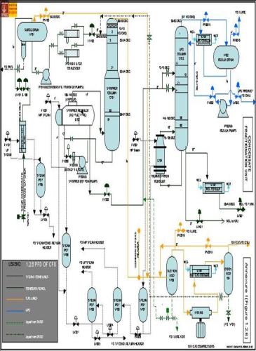
1.2.6 Process flow Diagram (PFD) (See Annexure I, Figure 1.2.6):
The operating parameters shown in the PFD are for ideal operating conditions. Pressure & temperature profiles are liable to vary from train to train depending upon the prevailing conditions of the reboilers, trays, heat exchangers, feed quality and location of the instrumentation sensors etc.
The PFD also includes the modification of the drain line from the compressor suction KOD to LPG Column in the Trains 72 & 76.
Condensate fractionation unit
1.2.7 Material Balance for CFU
1.2.7.1 ( Case1: 54 kg/cm2 at 33 deg C)
Stream No. | 1 | 2 | 3L | 3V | |||||||
Stream Name | Condensate from Slug catcher | Condensate surge drum vapour | Feed to Stripper | ||||||||
Liquid | Vapour | ||||||||||
Component name | M Wt. | Mole % | Kg mol/hr | Mole % | Kg mol/hr | Mole % | Kg mol/hr | Mole % | Kg mol/hr | ||
N2 | 28.01 | - | 0.01 | - | - | - | - | - | 0.01 | ||
H2S | 34.08 | 0.15 | 0.79 | 0.10 | 0.01 | 0.13 | 0.53 | 0.21 | 0.25 | ||
CO2 | 44.01 | 3.65 | 19.55 | 7.27 | 0.75 | 1.97 | 7.98 | 9.13 | 10.82 | ||
C1 | 16.04 | 20.93 | 112.03 | 77.23 | 7.97 | 6.45 | 26.20 | 65.73 | 77.86 | ||
C2 | 30.07 | 7.32 | 39.18 | 7.56 | 0.78 | 5.92 | 24.07 | 12.09 | 14.33 | ||
C3 | 44.09 | 12.26 | 65.08 | 4.84 | 0.50 | 13.42 | 54.55 | 8.47 | 10.03 | ||
iC4 | 58.12 | 4.56 | 24.42 | 0.97 | 0.10 | 5.54 | 22.53 | 1.51 | 1.79 | ||
nC4 | 58.12 | 7.56 | 40.44 | 7.16 | 0.12 | 9.39 | 38.14 | 1.84 | 2.18 | ||
iC5 | 72.15 | 3.61 | 19.31 | 0.29 | 0.03 | 4.63 | 18.83 | 0.38 | 0.45 | ||
nC5 | 72.15 | 4.24 | 22.67 | 0.29 | 0.03 | 5.47 | 22.23 | 0.35 | 0.41 | ||
C6 | 86.17 | 6.39 | 34.19 | 0.19 | 0.02 | 8.36 | 33.96 | 0.18 | 0.21 | ||
C7 | 100.20 | 7.69 | 41.12 | 0.10 | 0.01 | 10.10 | 41.03 | 0.07 | 0.08 | ||
C8 | 114.22 | 9.27 | 49.60 | - | - | 12.20 | 49.56 | 0.03 | 0.04 | ||
C9 | 128.25 | 4.81 | 25.77 | - | - | 6.34 | 25.76 | 0.01 | 0.01 | ||
C10 | 142.28 | 2.90 | 15.53 | - | - | 3.82 | 15.53 | - | - | ||
C11 | 156.30 | 3.29 | 17.60 | - | - | 4.33 | 17.60 | - | - | ||
C12 | 170.33 | 1.47 | 7.58 | - | - | 1.93 | 7.85 | - | - | ||
Total | 100.00 | 535.14 | 100.00 | 10.32 | 100.00 | 406.35 | 100.00 | 535.14 | |||
HC kg/hr | 35865 | 226 | 32707 | 2932 | |||||||
Water kg/hr | 200 | ||||||||||
Mol. Wt. | 67.02 | 21.90 | 80.49 | 24.75 | |||||||
Density kg/m3 | 597 | 52.10 | 640 | 20.93 | |||||||
Temp. o C | 33 | 35 | 27 | 27 | |||||||
Press. kg/cm2 | 54 | 52 | 18 | 18 | |||||||
Condensate fractionation unit
(1.2.7.1 Contd.) Material Balance for CFU (Case1: 54 kg/cm2 at 33 deg C)
Stream No. | 4L | 4V | 5 | 6 | ||||||||
Stream Name | Feed to LPG Column | LPG Feed to Caustic Wash Unit | NGL Product to Storage | |||||||||
Liquid | Vapour | |||||||||||
Component name | M Wt. | Mole % | Kg mol/hr | Mole % | Kg mol/hr | Mole % | Kg mol/hr | Mole % | Kg mol/hr | |||
N2 | 28.01 | - | - | - | - | - | - | - | - | |||
H2S | 34.08 | 0.5ppm | - | 6.3 ppm | - | 6.4 ppm | - | - | - | |||
CO2 | 44.01 | - | - | - | - | - | - | - | - | |||
C1 | 16.04 | - | - | - | - | - | - | - | - | |||
C2 | 30.07 | - | - | - | - | - | - | - | - | |||
C3 | 44.09 | 7.25 | 18.08 | 33.53 | 29.17 | 44.78 | 47.25 | - | - | |||
iC4 | 58.12 | 4.25 | 10.61 | 12.24 | 10.64 | 20.14 | 21.25 | - | - | |||
nC4 | 58.12 | 7.94 | 19.08 | 19.28 | 16.78 | 34.55 | 36.46 | 0.05 | 0.12 | |||
iC5 | 72.15 | 4.0 | 12.22 | 7.21 | 6.27 | 0.48 | 0.51 | 7.79 | 17.98 | |||
nC5 | 72.15 | 6.02 | 15.03 | 7.92 | 6.89 | 0.05 | 0.06 | 9.47 | 21.86 | |||
C6 | 86.17 | 10.82 | 26.99 | 7.82 | 6.81 | - | - | 14.63 | 33.80 | |||
C7 | 100.20 | 14.39 | 35.89 | 5.82 | 5.06 | - | - | 17.73 | 40.95 | |||
C8 | 114.22 | 18.41 | 45.94 | 4.13 | 3.59 | - | - | 21.44 | 49.53 | |||
C9 | 128.25 | 9.88 | 24.67 | 1.25 | 1.09 | - | - | 11.15 | 25.67 | |||
C10 | 142.28 | 6.07 | 15.15 | 0.43 | 0.38 | - | - | 6.72 | 15.53 | |||
C11 | 156.30 | 6.95 | 17.34 | 0.29 | 0.26 | - | - | 7.62 | 17.60 | |||
C12 | 170.33 | 3.12 | 7.78 | 0.08 | 0.07 | - | - | 3.40 | 7.85 | |||
Total | 100.00 | 249.50 | 100.0 | 87.01 | 100.00 | 105.53 | 100.00 | 230.98 | ||||
HC kg/hr | 25056 | 5577 | 5479 | 25154 | ||||||||
Water kg/hr | - | |||||||||||
Mol. Wt. | 100.442 | 64.10 | 51.98 | 108.90 | ||||||||
Density kg/m3 | 577 | 22.07 | 529 | 667 | ||||||||
Temp. o C | 144 | 144 | 45 | 45 | ||||||||
Press. kg/cm2 | 10.4 | 10.4 | 15.5 | 5 | ||||||||
Condensate fractionation unit
(1.2.7.1 Contd.) Material Balance for CFU (Case1: 54 kg/cm2 at 33 deg C)
Stream No. | 7 | ||
Stream Name | Vapour from stripper (Offgas) | ||
Component name | M Wt. | Mole % | Kg mol/hr |
N2 | 28.01 | - | 0.01 |
H2S | 34.08 | 0.41 | 0.78 |
CO2 | 44.01 | 9.98 | 18.80 |
C1 | 16.04 | 55.26 | 104.6 |
C2 | 30.07 | 20.39 | 38.40 |
C3 | 44.09 | 9.20 | 17.33 |
iC4 | 58.12 | 1.63 | 3.07 |
nC4 | 58.12 | 1.99 | 3.74 |
iC5 | 72.15 | 0.42 | 0.79 |
nC5 | 72.15 | 0.38 | 0.72 |
C6 | 86.17 | 0.20 | 0.37 |
C7 | 100.20 | 0.09 | 0.16 |
C8 | 114.22 | 0.04 | 0.07 |
C9 | 128.25 | 0.01 | 0.01 |
C10 | 142.28 | - | - |
C11 | 156.30 | - | - |
C12 | 170.33 | - | - |
Total | 100.00 | 188.31 | |
HC kg/hr | 5006 | ||
Water kg/hr | |||
Mol. Wt. | 26.58 | ||
Density kg/m3 | 20.73 | ||
Temp. o C | 31 | ||
Press. kg/cm2 | 18.0 | ||
Condensate fractionation unit
1.2.7.2 Material Balance for CFU ( Case2: 93 kg/cm2 at 33 deg C)
Stream No. | 1 | 2 | 3L | 3V | |||||
Stream Name | Condensate from Slug catcher | Condensate surge drum vapour | Feed to Stripper | ||||||
Liquid | Vapour | ||||||||
Component name | M Wt. | Mole % | Kg mol/hr | Mole % | Kg mol/hr | Mole % | Kg mol/hr | Mole % | Kg mol/hr |
N2 | 28.01 | - | 0.02 | 0.01 | 0.01 | - | - | 0.01 | 0.01 |
H2S | 34.08 | 0.18 | 1.36 | 0.14 | 0.13 | 0.17 | 0.75 | 0.21 | 0.48 |
CO2 | 44.01 | 5.27 | 40.46 | 7.56 | 7.15 | 2.71 | 12.11 | .31 | 21.20 |
C1 | 16.04 | 34.68 | 266.56 | 76.22 | 72.14 | 9.15 | 40.82 | 67.45 | 153.60 |
C2 | 30.07 | 8.91 | 68.51 | 7.2 | 7.50 | 7.62 | 34.02 | 11.85 | 26.99 |
C3 | 44.09 | 11.75 | 90.32 | 5.03 | 4.76 | 15.28 | 68.18 | 7.63 | 17.36 |
iC4 | 58.12 | 3.77 | 28.99 | 0.5 | 0.90 | 5.65 | 25.22 | 1.26 | 2.87 |
nC4 | 58.12 | 5.95 | 45.74 | 1.19 | 1.13 | 9.24 | 41.21 | 1.49 | 3.40 |
iC5 | 72.15 | 2.54 | 19.49 | 0.29 | 0.27 | 4.16 | 18.55 | 0.29 | 0.67 |
nC5 | 72.15 | 2.91 | 22.40 | 0.28 | 0.26 | 4.83 | 21.54 | 0.26 | 0.60 |
C6 | 86.17 | 4.17 | 32.03 | 0.19 | 0.18 | 7.07 | 31.54 | 0.14 | 0.31 |
C7 | 100.20 | 5.02 | 38.59 | 0.12 | 0.11 | 8.59 | 38.35 | 0.06 | 0.13 |
C8 | 114.22 | 6.20 | 47.64 | 0.07 | 0.07 | 10.65 | 47.51 | 0.03 | 0.06 |
C9 | 128.25 | 3.29 | 25.29 | 0.02 | 0.02 | 5.66 | 25.26 | 0.01 | 0.01 |
C10 | 142.28 | 2.02 | 15.50 | 0.01 | 0.01 | 3.47 | 15.49 | - | - |
C11 | 156.30 | 2.31 | 17.73 | - | - | 3.97 | 17.73 | - | - |
C12 | 170.33 | 1.03 | 7.96 | - | - | 1.78 | 7.96 | - | - |
Total | 100.00 | 768.59 | 100.00 | 94.64 | 100.00 | 446.24 | 100.00 | 227.71 | |
HC kg/hr | 41154 | 2106 | 33553 | 5495 | |||||
Water kg/hr | 200 | ||||||||
Mol. Wt. | 53.54 | 22.25 | 75.19 | 24.13 | |||||
Density kg/m3 | 551 | 88 | 627 | 26.2 | |||||
Temp. o C | 33 | 39 | 27 | 27 | |||||
Press. kg/cm2 | 93 | 80 | 25 | 25 | |||||
Condensate fractionation unit
(1.2.7.2 Contd.) Material Balance for CFU (Case2: 93 kg/cm2 at 33 deg C)
Stream No. | 4L | 4V | 5 | 6 | ||||||
Stream Name | Feed to LPG Column | LPG Feed to Caustic Wash Unit | NGL Product to Storage | |||||||
Liquid | Vapour | |||||||||
Component name | M Wt. | Mole % | Kg mol/hr | Mole % | Kg mol/hr | Mole % | Kg mol/hr | Mole % | Kg mol/hr | |
N2 | 28.01 | - | - | - | - | - | - | - | - | |
H2S | 34.08 | 0.4 ppm | - | 4.3ppm | - | 5.7ppm | - | - | - | |
CO2 | 44.01 | - | - | - | - | - | - | - | - | |
C1 | 16.04 | - | - | - | - | - | - | - | - | |
C2 | 30.07 | - | - | - | - | - | - | - | - | |
C3 | 44.09 | 6.33 | 12.89 | 31.76 | 45.56 | 48.09 | 58.25 | - | - | |
iC4 | 58.12 | 3.58 | 7.18 | 11.45 | 16.42 | 19.48 | 23.60 | - | - | |
nC4 | 58.12 | 6.64 | 13.12 | 18.09 | 25.95 | 32.33 | 39.16 | 0.05 | 0.11 | |
iC5 | 72.15 | 4.10 | 8.22 | 6.92 | 9.93 | 0.09 | 0.11 | 8.10 | 18.04 | |
nC5 | 72.15 | 5.06 | 10.14 | 7.69 | 11.04 | 0.01 | 0.01 | 9.50 | 21.17 | |
C6 | 86.17 | 9.67 | 19.39 | 8.33 | 11.95 | - | - | 14.07 | 31.34 | |
C7 | 100.20 | 14.08 | 28.22 | 6.99 | 10.03 | - | - | 17.17 | 38.25 | |
C8 | 114.22 | 19.68 | 39.45 | 5.59 | 8.02 | - | - | 21.30 | 47.47 | |
C9 | 128.25 | 11.26 | 22.58 | 1.86 | 2.67 | - | - | 11.33 | 25.25 | |
C10 | 142.28 | 7.23 | 14.50 | 0.69 | 0.99 | - | - | 6.95 | 15.49 | |
C11 | 156.30 | 8.49 | 17.02 | 0.50 | 0.71 | - | - | 7.96 | 17.73 | |
C12 | 170.33 | 3.88 | 7.77 | 0.13 | 0.19 | - | - | 3.57 | 7.96 | |
Total | 100.00 | 200.48 | 100.00 | 143.46 | 100.0 | 121.13 | 100.00 | 222.81 | ||
HC kg/hr | 21022 | 9562 | 6224 | 24360 | ||||||
Water kg/hr | - | |||||||||
Mol. Wt. | 104.86 | 65.65 | 51.38 | 109.33 | ||||||
Density kg/m3 | 570 | 22.74 | 528 | 665 | ||||||
Temp. o C | 156 | 156 | 43 | 45 | ||||||
Press. kg/cm2 | 10.4 | 10.4 | 15.5 | 5 | ||||||
Condensate fractionation unit
(1.2.7.2 Contd.) Material Balance for CFU (Case2: 93 kg/cm2 at 33 deg C)
Stream No. | 7 | ||
Stream Name | Vapour from stripper (Offgas) | ||
Component name | M Wt. | Mole % | Kg mol/hr |
N2 | 28.01 | - | 0.01 |
H2S | 34.08 | 0.37 | 1.23 |
CO2 | 44.01 | 10.10 | 33.31 |
C1 | 16.04 | 58.91 | 194.42 |
C2 | 30.07 | 18.49 | 61.01 |
C3 | 44.09 | 8.28 | 27.31 |
iC4 | 58.12 | 1.36 | 4.49 |
nC4 | 58.12 | 1.62 | 5.34 |
iC5 | 72.15 | 0.32 | 1.07 |
nC5 | 72.15 | 0.29 | 0.96 |
C6 | 86.17 | 0.16 | 0.51 |
C7 | 100.20 | 0.07 | 0.23 |
C8 | 114.22 | 0.03 | 0.10 |
C9 | 128.25 | - | 0.02 |
C10 | 142.28 | - | - |
C11 | 156.30 | - | - |
C12 | 170.33 | - | - |
Total | 100.00 | 330.91 | |
HC kg/hr | 8464 | ||
Water kg/hr | |||
Mol. Wt. | 25.65 | ||
Density kg/m3 | 28.16 | ||
Temp. o C | 31 | ||
Press. kg/cm2 | 25 | ||
Condensate fractionation unit
2.0 PROCESS DESIGN
2.1 PROCESS DESCRIPTION
Condensate Fractionation Unit is designed to remove H2S and to recover LPG & NGL from slug-catcher condensate.
The fractionation Unit consists of
-Condensate receiving system
-H2S Stripper
-Condensate-Offgas compression
-LPG Column.
2.1.1 Condensate Receiving System
The condensate as it comes from the slug-catcher is heated in a condensate preheater (E701) and received in Surge Drum (V701) under level control through LCVs LV1101 & LV1106. The preheater uses LP steam to heat the condensate upto 33 oC to 36 oC to avoid any hydrate formation. Hydrate formation is possible if there is high pressure drop across control valves.
The flash vapour from the surge drum V701 is taken to gas sweetening unit directly (bypassing compressor) when condensate inlet pressure is at 80 kg/cm2 or more. Below 80 kg/cm2, the pressure is maintained 2 kg/cm2 below the inlet pressure in the surge drum to allow differential for incoming liquid and the vapour is routed through the compressor system.
Any free water droplets get separated in the surge drum and collect in boot of V701. Water level is drained through interface level control mechanism. The condensate in the surge drum V701 is taken into Condensate Transfer pumps P701A/B (one operating & one stand by). This pump is provided to generate sufficient head & flow to avoid any condensate flashing in the down stream Filter-Coalescer X701A/B.
Two unit of cartridge type Filter-Coalescer are provided (one operating & one stand by). The filtering elements of the filter are being used for filtering out any scale/dust/debris/Iron sulphides/black material which may entail during pre-commissioning/commissioning, pigging operation of the trunk lines.
Condensate fractionation unit
The coalescer element is used for removal of free water. The free water collected in the boot and is drained through interface level control mechanism. The condensate flows further through flow control valve FV1102 into the stripper column top tray. This is designed to maintain a back pressure to ensure that no flashing occurs in the filter chamber.
Dew Point Depression Unit’s condensate can also be processed in CFU besides LPG plant as and when required so.
2.1.2 H2S Stripper
Stripper Column C701 is designed to strip off H2S from the sour condensate such that the condensate at the bottom reaches maximum of 4 ppm H2S and to retain maximum C3 & C4 in the condensate at pressure of 18 to 18.5 kg/cm2 at the prevailing inlet pressure.
Feed to the stripper is a liquid at the upstream and flashes as liquid-vapour mixture in the space above the first tray of the column C701 of 61 valve type trays. The first 20 trays on the top section are single pass trays and the bottom section of 40 trays is double pass trays. The separated liquid trickles down the column and the vapour escapes from the top as offgas. The Offgas Stripper bottom liquid is pumped through P703A/B pumps to reboiler E702 via basket type filters X702A/B to remove any suspended particles which may foul the reboiler. However, in view to conserve energy, these filter pumps were stopped on experimental basis to observe the satisfactory operation if possible without them running. Effectively, these pumps & filter assembly were bypassed since 1999.
A kettle type reboiler E702 is provided at the Stripper C701 bottom which utilizes MP steam for heating. Steam flow is controlled through FV201 to ensure stripping vapour at 135 to 145 oC & thereby maintain stripper bottom temperature at 93 to 97 oC.
Bottom of C701 is sweet Condensate and is withdrawn from reboiler under level control cascaded with flow control valve FV202 to LPG Column C702
Condensate fractionation unit
2.1.3 LPG Column
The stripper bottom liquid is taken to LPG column (C702) at 24th or 19th from top. This column has 60 trays and is designed to separate LPG (propane and butanes) from heavier components. The column operates at 9.7kg/cm2a pressure. This pressure has been chosen to keep overhead condensing temperature at 43 oC, so that cooling water can be used in the overhead condenser (E703).
Reflux ratio from 1.5-2.0 is maintained in the column depending upon the operating case. Butane recovery of more than 99.55 % is achieved at design reflux. LPG is taken as overhead liquid product through the LPG reflux and transfer pumps (P702 A/B) under level control of reflux drum (V702).
The column bottom has a thermo-siphon type reboiler (E704) using high pressure steam. Column bottom temperature varies from 175 to 185 oC depending upon operating case. NGL is withdrawn as bottom product and sent to Kerosene Recovery Unit for further processing or cooled to 45 oC by cooling water in NGL cooler E-705 and sent to storage in offsites as the case may be.
Most of Hydrogen sulfide (about 4 ppm) present in LPG column feed appears in LPG product resulting in 5 - 20 ppm concentrations. This LPG is sweetened in a caustic wash unit (Bubbling of LPG liquid in static bed of 15% caustic Soda solution) is off sites and sent to storage.
2.1.4 Off-gas Compression
The stripper overhead vapor is taken to compressor suction K.O.Drum (V703). The surge drum flashed vapor is also combined with this stream. Two numbers reciprocating compressors 701 A/B (one operating & one standby) are provided in phase-I, II, III to compress this sour gas and form the feed to gas sweetening units. The compressor discharge gas is cooled to 45 oC using cooling water in exchanger E706. Gas temperature is selected about 10 oC higher than dew point to avoid condensation and production of sour condensate. This eliminates sour condensate recycle within the system. The cooled gas is sent to GSU through compressor discharge KOD drum V704.
Condensate fractionation unit
CFU off-gas compressor has been deleted for the Train 77 with the idea to utilize the existing under utilized compressor provided for this purpose under Phase I, Phase-II and Phase-III. CFU-off gas from this train shall be routed to the common suction header of these compressors (the compressors have been integrated.). The deletion of CFU off gas compressors has necessitated a slight change in the control scheme of the stripper column and the compression circuit. In the earlier trains the compressors have been provided with a pressure control at the suction and the stripper column floats on the suction pressure of the compressor. In the present train the stripper column shall operate at a slightly higher pressure and its pressure control shall be independent of the suction pressure control of the existing compressor.
Condensate fractionation unit
2.2 Utilities System
Condensate fractionation is located in a single block. For all process and utility lines, block boundary has been treated as B/L. All process and utility headers within B/L are common.
2.2.1 Steam/Condensate System
The steam condensate from all heaters/reboilers is taken through level control of steam Condensate pots. The high pressure condensate coming from the LPG column reboiler is flashed to produce MP steam in HP condensate flash drum (V708).
The MP condensate coming from (V708) and stripper reboiler (E702) is flashed to produce LP steam in MP condensate flash drum (V709). The final low pressure condensate from V709 and feed condensate heater (E701) will be sent back to B/L.
2.2.2 Flare System
A common flare header, flare K.O drum and flare blow down pumps are provided within B/L. All the hydrocarbon vapors/liquid collected from vents and pressure relief valves will go to flare K.O drum through flare header. From the gas goes over to a flare stack through an off site flare header. The liquid collected from flare K.O drum will be pumped to NGL Tank located in off sites.
Tag Nos. of Flare KODs and Pumps:
1) 70V 756 P 752 A/B Phase-I
2) 70V 761 P 761 A/B Phase-II
3) 70V 781 P 781 A/B Phase III
4) 70V 791 P 791 A/B Phase IIIA
2.2.3 Instrument air, plant air, service water, inert gas, are received at B/L and supplied within unit through headers.
2.2.4 UTILITY CONSUMPTIONS
The normal utility requirements are listed in utility summary shown at the following page.
Condensate fractionation unit
UTILITY SUMMARY (Case: 54 Kg/cm2 a, 33 o C) | ||||||||||||||||
ITEM No. | SERVICE | Elec. Power | Steam (Kg/cm2) | Water | Fuel | N2 | Air | |||||||||
KW | HP(33) | MP(18) | LP(8) | Cond. | Loss | CW | DMW | SOFT | RAW | GAS | Oil | LA | PA | |||
Kg/Hr | M3/hr | Kg/hr | Nm3/hr | Nm3/hr | ||||||||||||
E701 | Condenser heater | 1808 | -1808 | |||||||||||||
E702 | Stripper reboiler | 9097 | ||||||||||||||
E703 | LPG col. condenser | 232 | ||||||||||||||
E704 | LPG thermo siphon reboiler | 6766 | ||||||||||||||
E705 | NGL Cooler | 262 | ||||||||||||||
E706 | Compressor discharge cooler | 262 | ||||||||||||||
V705 | LP cond. Flash Drum | |||||||||||||||
V706 | MP Cond. Flash Drum | |||||||||||||||
V707 | HP Cond. Flash Drum | -669 | ||||||||||||||
V708 | MP Cond. Flash Drum | |||||||||||||||
V709 | MP Cond. Flash Drum | -1559 | -13635 | |||||||||||||
P701A/B | Cond. Transfer pump | 26.9 | ||||||||||||||
P702A/B | LPG Reflux pump | 22.6 | ||||||||||||||
P703A/B | Stripper bottom pump | 21.9 | ||||||||||||||
Flare header | 50 | |||||||||||||||
Instruments | 200 | |||||||||||||||
Hose connections | 10* | 170* | 170* | |||||||||||||
Total | Total | 71.4 | 6766 | 8428 | 249 | -15443 | 756 | 50 | 200 | |||||||
NOTE: The values marked with (*) represent intermittent utility and not included in the total figure | ||||||||||||||||
Condensate fractionation unit
2.3 Chemical System
2.3.1 Methanol System
A common methanol pot with methanol injection pumps are provided with B/L. Methanol will be received in the pot from offsite. This methanol is used to prevent/melt out hydrates in process unit during upset condition but since commissioning such problem has never been encountered in any CFU train.
Quality : Commercial
Quantity : 3 m3 as initial fill. More methanol may be required depending upon process conditions encountered during starting and normal operation.
TAG NOS. OF METHANOL POTS & PUMPS:
1) 70 T 751 P 753 A/B Phase I
2) 70 T 761 P 762 A/B Phase II
3) 70 V 782 P 782 A/B Phase III
4) 70 V 792 P 792 A/B Phase IIIA
2.3.2 Other Chemicals
Other chemical required during construction and commissioning have to be arranged by contractor as per following list, and not limited to, depending upon specific needs.
- Lubricating oils etc. as per equipment vendor recommendation.
Condensate fractionation unit
2.4 Effluent Summary
Effluent from this plant is categorized as follows:
a) Liquid effluents comprising of process oily water, vessels drains and washings and storm water effluents.
b) Gaseous effluents from vessels and safety valve discharges
2.4.1 Liquid Effluents
In normal operation, there will be continuous and/or intermittent drainage of water from some vessels, drains, e.g surge drum, filter coalescers, and compressor KO. Drums, which is likely to be associated with dissolved hydrocarbons and hydrogen sulphide. Another source is occasional leakages/drippings of lubricating oils around the various rotating equipment like pumps and compressors.
During floor washings, waste water is generated which is likely to be contaminated with oil. During rainy seasons there are chances of rain/storm water also getting contaminated with oil.
All the above form liquid effluent. This effluent can be treated in centralized effluent treatment plant located in offsite area and hence, no primary treatment is necessary within process unit block. These effluents are collected in common Oily Water Sewer (OWS) system from where these are sent to a central waste water treatment plant.
The summary of liquid effluents coming out of the condensate fractionation unit is given in Table - 2.
Condensate fractionation unit
TABLE-2
LIQUID EFFLUENT SUMMARY
FOR CONDENSATE FRACTIONATION UNIT
DESCRIPTION | PROCESS DRAINS | UNIT FLOOR WASHING | CONTAMINATED RAIN WATER FROM PAVED AREA |
FLOW RATE,M3/HR AVG/PEAK | .5/1.0 | -/15 | NOTE-1 |
FREQUENCY OF FLOW CONTINUOUS/INTERMITTENT | CONT/INT | -/INT | -/INT |
DURATION OF INTERMITTENT,HR | 1.0 | 2.0 | NOTE-1 |
TEMPERATURE, C | AMB | AMB | AMB |
PRESSURE,KG/CM2a | ATM | ATM | ATM |
COLOUR/ODOUR | CLEAR/H2S | CLEAR/- | CLEAR/- |
SP.GRAVITY | 1.0 | 1.0 | 1.0 |
VISCOSITY, Cp | 0.7-1.0 | 0.7-1.0 | 0.7-1.0 |
pH | 6-9 | 6-9 | 6-9 |
BOD mg/lit | 300 | 100 | 300 |
COD, mg/lit | - | - | - |
SUSPENDED SOLIDS, mg/lit | 150 | NOT AVAIL | NOT AVAIL |
TOTAL DISSOLVED SOLIDS, mg/lit | NIL | DO | DO |
TOTAL OIL & GREASE CONTENT,PPM (MAX) | 300 | 300 | 300 |
a) SP.GR. OF OIL | 0.6-0.9 | 0.6-0.9 | 0.6-0.9 |
b) viscosity of oil, Cp | 0.2-0.8 | 0.2-15 | 0.2-15 |
SULPHIDE CONTENT, mg/lit | 5 | - | - |
PHENOL, mg/lit | -- | --- | -- |
NOTE:
This data will be available from detailed engineering.
The oil contamination will be light naphtha (highly volatile in process drain water and machine oil (lube oil) in floor washing and contaminated rain water.
Condensate fractionation unit
2.4.2 Gaseous Effluents
In normal circumstances there will not be any gaseous effluents, excepting small quantities from occasional gas venting from some equipment. However, during upset conditions, safety valves discharges will occur. Also, in event of one of condensate fractionation train shutdown, condensate stabilization unit will be operated and hence, continuous gaseous effluent will be generated.
For this a common elevated flare with ground box flare system has been provided in offsite. All the gaseous effluent will be routed through unit flare KO. Drum and diverted to offsite flare header for burning.
The gaseous effluent for various plants operating conditions are listed on Table - 3.
TABLE-3
GASEOUS EFFLUENTS FOR CONDENSATE FRACTIONATION UNIT
FIRE | POWER/COOLING WATER FAILURE | BLOCK DISCHARGE | MECHANICAL FAILURE | ||||||||
T/HR | M.WT. | C | T/HR | M.WT | C | T/HR | M.WT | C | T/HR | M.WT | C |
124 | 27 | 60 | 89 | 45 | 50 | 755 | 50 | -10 | 130 | 50 | -10 |
Condensate fractionation unit
3.0 PLANT SHUTDOWN PROCEDURE
3.1 GENERAL
A planned shutdown is a non-emergency shutdown such as annual turn-around.
As the Condensate Fractionation Unit is connected with other downstream units, the process supervisors of this unit should be advised before any scheduled shutdown.
During a shutdown all equipment isolation valves should be closed to minimize the release of hydrocarbons.
Two types of normal shutdown (short duration and long duration) and purging procedures are presented in this chapter. The major difference between the two types of normal shutdown is that for the long duration shutdown, it is recommended that all the equipments be completely drained and purged.
3.2 PLANNED SHUT-DOWN (SHORT DURATION)
On a normal shutdown the feed to the unit should be slowly reduced in a stepwise manner to minimize disturbances to the downstream process units and utility system.
For shutdowns of a very short nature, i.e. less than a shift consideration should be given to blocking in the unit and storing the condensate in slug catcher.
3.2.1 Slowly reduce the slug catcher condensate feed to 40% design in steps of 5% of design flow.
3.2.2 When the unit has been reduced to 40% of design flow start reducing the temperature of columns (C701, C702). This is done by reducing M.P steam to stripper reboiler E702 and H.P steam flow to LPG column reboiler E-704. If the off-gas from the surge drum (V701) is flow to the gas sweetening unit through the compressor by-pass line (4"-P-1103-1), switch over to the compressor suction drum when pressure starts falling below 80 kg/cm2a, set PIC1102 to 2 kg/cm2 below the condensate arrival pressure.
3.2.3 Close the stripper C701 feed by closing the FV1102.
3.2.4 Close the block valve on P701 A or B discharge line.
3.2.5 Stop the P701.
3.2.6 Close the block valves at the battery limit of LPG and NGL product.
3.2.7 Keep the LPG column reflux/transfer pump P702 A/B on circulation until LPG column has cooled down and level in reflux drum V-702 is at 20%.
3.2.8 Close shutdown valve SDV-1101.
Condensate fractionation unit
3.2.9 Slowly reduce the steam supply to heat exchangers, Condensate heater E701, Stripper reboiler E702, and LPG reboiler E704.
3.2.10 When the level in associated vessels have stabilized at 50%, block in the following control valves, LV-1101/1106, LV1102, LV1202.
3.2.11 The loads of compressor have been reduced to control the compressor suction pressure and the pressure control valve PV1201A has been opened widely. Now, ensure total recycle during short period.
3.2.12 Stop the LPG column reflux/transfer pump P702 A/B when level in V702 has reduced 20%.
NOTE: Careful watch on all pressures, temperatures, levels and rotating equipments during this period is required. Make necessary adjustments so that restart can progress safety without too much delay.
3.3 PLANNED SHUT-DOWN (LONG DURATION)
For plant long duration shutdown, plant would be stopped as per procedure outlined for short duration.
Further all the equipment in the Condensate Fractionation Unit should be drained of liquid hydrocarbons and the plant depressurized to flare before purging all the equipment.
3.3.1 Keep LPG column C702 pressure at 10 kg/cm2a by adjusting the steam flow to reboiler.
3.3.2 Slowly reduce the pressure of condensate surge drum (V-701) to 27 kg/cm2a.
3.3.3 Stop the compressors K701 A/B as per manufacturer’s instructions.
3.3.4 Start P701 A/B and pump out the condensate from the surge drum V701 until just before it evacuates.
3.3.5 Slowly transfer the liquid from coalescer filter X701A/B through FV102 bypass into the stripper column.
Note: Watch carefully when emptying X-701 A/B to prevent gas break through into the strippers, as it could disturb the trays and stripper, as it could disturb the trays and demister pad.
3.3.6 Start P703 A/B to transfer he liquid level in the bottom of stripper (C701) and reboiler to LPG column (C702). Stop P703 A/B just before it starts to evacuate.
Condensate fractionation unit
3.3.7 Start P702 A/B to pump out LPG level in reflux drum (V702) to caustic wash unit in offsites. Stop P702 A/B just before the level low-low is reached.
3.3.8 Transfer the liquid level from LPG column C702 and reboiler E704 to storage with system pressure.
3.3.9 Shut off the steam supply to E704 when levels are minimum.
3.3.10 Depressurise the entire unit to the flare system.
3.3.11 Drain any liquid levels to oily water sewer after checking that the system is completely depressurized.
3.3.12 Close the block valves of suction line and discharge line of compressor K 701A/B.
3.3.13 Open the inert gas valve and purge out compressor with inert gas.
3.3.14 Turn spectacle blinds on suction & discharge of the compressor K701 A/B.
3.3.15 Purge the compressor with inert gas leave it under positive pressure.
3.3.16 Close the all drains and flare system.
3.3.17 Open block valves on inert gas connection line to X- 701 A/B and connect the inert gas to vessels from the hose stations. Purge out hydrocarbons from the unit.
3.3.18 Pressurize entire unit, up to 7.0 kg/cm2/a, with inert gas.
3.3.19 Depressurize the entire unit to flare system through all vent connections. Depressurize the unit to 0.1 kg/cm2g Repeat above steps 18, 19 more than three times until hydrocarbon content is below 0.5 vol%. Check and ensure that hydrocarbon content is below 0.5 vol % through the unit with a portable analyzer. Leave a pressure of 0.4 or O.7 kg/cm2g on the unit at the time final depressurizing is done. If hydrocarbon content is above 0.5 vol% depressurize to 0.1 kg/cm2g and repeat steps until hydrocarbon content is less than 0.5 vol%. Check hydrocarbon content in dead ends of pipes and ensure that hydrocarbon in liquid is blown through. Any hydrocarbon condensate accumulated in the vessel should be drained to the oily water sewer.
Condensate fractionation unit
3.3.20 Close all connections to flare when all lines and equipment have been purged.
3.3.21 Turn the spectacle blinds at unit battery limits to their closed position. The condensate fractionation unit, except flare and blow down system are now completely isolated and are ready for maintenance and inspection. The equipment and lines which shall not be opened for maintenance to be left at slight overpressure using inert gas or nitrogen. Maintenance personnel shall not enter any equipment without proper oxygen apparatus unless the unit has been purged entirely with air to displace all inert gas.
3.4 EMERGENCY SHUT-DOWN
3.4.1 Types of Emergency Shut-down
Emergencies will generally require an immediate complete stoppage of operation with at least part of the plant shutdown and depressurized. In most instances, hydrocarbon must be eliminated to the maximum extent possible in the shortest time as determined by the urgency of the emergency. In some cases, the type of shutdown is complicated by the emergency situation itself, requiring in many cases a split-second decision by the operator.
Conduct all emergency shutdowns in the most economical manner possible with primary considerations for the safety of personnel, with secondary concern to safeguarding the equipment and still less priority reserved for products quality.
Determine the cause of the emergency including the exact situation: and if possible, revert to a normal shutdown at the first opportunity.
A unit shutdown system is provided to allow shutting down all incoming gas, treated and acid gas.
Emergency shutdowns may be caused by:
-Automatic shutdown following a programmed sequence and resulting for example from a product/utility failure.
-Manual shutdown entailed by an emergency or induced to avoid an accident.
Condensate fractionation unit
It is difficult to predict all the possible causes of emergency shutdown and to define, for each case, the actions to be taken.
Recommendations hereafter, are only partial guidelines; the actual shutdown procedure will be defined in function of the actual situation and operators troubleshooting capability.
3.4.2 Action during emergency shut-down;
3.4.2.1Low levels in condensate surge drum V-701. The following automatic actions will take place on LSLL1111 being activated.
Stops P701A/B
Close FV1102.
The following manual action should be taken by operator;
Put FIC1201 stripper reboiler on manual control and close it.
Close LV1202 to maintain level in stripper C701.
Reduce reflux to LPG column (C702) to maintain level in reflux drum (V702)
Maintain unit continuous until the level is restored in surge drum V701
3.4.2.2High level in surge drums V701.
The following automatic action will take place on LSHH-1108/LSHH1109.;
Close LV1101
Close LV1106
Shut off SDV1101
Close steam supply valve FV1101 to condensate heater.
The following manual action should be taken by operator;
Start P701 spare pump
Condensate fractionation unit
When level returns to normal condition, following actions should be taken;
· Latch open shutdown valves.
· Put LIC1101/1106 on manual control and feeding in condensate to the surge drum (V701).
· Open FV1101 and supply the steam to condensate heater E701 then, control the temperature of condensate.
3.4.2.3Low water level in surge drum (V701) boot;
ILSLL1114 will be activated and shut off SDV1102 emergency shutdown valve automatically.
The following manual action should be taken by operator;
· Put LV1102 on manual control and close it.
· Unlatch the SDV1102 when interface level is established
3.4.2.4Pressure high in feed inlet to the surge drum
V701;
PSHH1108/1109 will be activated and following actions will happen automatically.
· Shut off emergency shutdown valve SDV1101
· Close steam control valve FV1101
· Close LV1101/1106
The following actions should be taken by operator;
· Reduce feed to the stripper by closing FV1102.
· Open the compressor bypass line.
· Check PV1102. If it has fail closed, open by-pass valve slowly.
Condensate fractionation unit
3.4.2.5Low temperature of Stripper feed;
TALL1109 will be activated and following actions will take place automatically;
· Close emergency shutdown SDV1101
· Close LV1106 & LV1101
· Close steam control valve FV1101 to E701.
Following actions should be taken by the operator;
· Decrease the feed flow to the stripper C701 by closing FV1102
· Check steam system and the condensate system.
After the problem has been overcome;
· Activate the start up switch located on the panel to bypass TALL1109.
· Reset SDV1101
· Reset LV1101 & 1106 manually.
· Reset FV1101 manually.
· Supply LP steam to E701
· Slowly start feeding the condensate to Surge Drum.
3.4.2.6High pressure steam to condensate heater
PSHH 1106 will be activated and following actions will take place automatically;
· Close SDV1101-Emergency shutdown valve.
· Close LV1101 & LV1106
· Close steam flow control valve FV1101.
Following actions to be taken by the Operator;
· Reduce the feed flow to stripper
· Check steam system for any tube failure
· Bleed off excess steam pressure.
· Reset SDV 1101 manually
· Reset LV1101 & LV1106 manually
· Reset FV1101 on to manual control & close it.
· Bring unit to normal conditions.
Condensate fractionation unit
3.4.2.7Low level in slug catcher;
Trip signal will ensue at Gas Terminal and following actions to be followed;
· Close emergency shut down valve.
· Close LV 1101 & 1106
· Close FV1101
Following actions should be taken by the operator;
· Put FV1102 on manual control & close FV1102.
· Stop condensate transfer pump P701A/B.
· Slowly reduce steam flow and close FV1201, FV301.
· Close Level control valves to retain liquid levels in columns & drums.
3.4.2.8Low water level in filter coalescer boot;
LSLL1117 & LSLL1120 in X701A & X701B respectively will actuate and following actions will take place automatically;
· Shut off SDV1103 or SDV1104
· Close ILV1103 or ILV1104.
After interface level is established, reset SOV manually and put controller on auto at 30% level.
3.4.2.9High pressure in the stripper Column C701;
PSHH1207 will be actuated and FV201 will close automatically.
Following actions should be taken by the Operator;
· Check if compressor K701A/B is running OK.
· Check DP across stripper- If high decrease feed rate.
· Check column bottom temperature
· Check condensate arrival pressure.
Condensate fractionation unit
3.4.2.10 Low level in the stripper column
LSLL 1206 will be actuated and P703A/B will trip on interlock. Following actions to be taken by the operator;
· Put FV1202 on manual control
· Increase feed to stripper temporarily
· Close LPG column level control valve LV1301/1302
· Regulate FV1201
3.4.2.11 High pressure in LPG column C702
PSHH1303 will be actuated and FV1301 will close on interlock. Following actions to be taken by the operator;
· Check column overhead pressure
· If too high and PV1301B is fully open, close PV1301A.
· Check DP across the column C702
· Check column bottom temperature TI1302
· Check overhead temperature TI1304
· Check reflux pump P702A/B
· Check reflux control valve FV1301
3.4.2.12 Instrument Air failure
The unit will automatically trip and short-duration shutdown procedure should be followed.
3.4.2.13 Steam supply failure
· LP steam failure: Reduce the feed such as to keep temperature above set point of TALL1110.
· MP steam failure: Reduce the feed. If goes below 40% of the design flow, short duration shutdown to be followed.
· HP steam failure: Reduce the feed to stripper and reduce LPG column reflux. Try matching feed with available heat supply. If goes below 40% of the design flow, short duration shutdown to be followed.
Condensate fractionation unit
3.4.2.14 Cooling water failure;
Reduce the condensate feed and increase the LPG column reflux. Try to stabilize the LPG column. . If the feed goes below 40% of the design flow, short duration shutdown to be followed
Condensate fractionation unit
3.5 COMPRESSOR STOPPING PROCEDURE:
3.5.1 Unload the compressor by operating the unloader switch on the Local panel to unload the suction unloader-valves thereby reaching a state of no compression in the compressor cylinders.
3.5.2 Then the motor of the compressor is be stopped by the push button on the local panel.
3.5.3 Let the Auxiliary Lube oil pump run on auto mode for sometime (5 minutes or so). Stop the pump after switching it on manual mode.
The above three steps will bring compressor to Stand-by. For complete shutdown of the compressor system for maintenance work, following steps should be followed;
3.5.4 Close the discharge line isolation valve.
3.5.5 Close the suction line isolation valve.
3.5.6 Relieve the pressure in the compressor system to flare by the vent line provided.
3.5.7 Charge the system with nitrogen for purging.
3.5.8 For longer shut downs, isolate the cooling water supply to the lube oil cooler & cylinder jackets. Unless required so, the ethylene glycol solution provided for jacket cooling should not be drained.
3.5.9 Open the drain points provided at the bottom pockets of the compressor after the purging is done & the sample of the same is acceptable.
3.5.10 For longer duration shutdowns;
· All cylinders/volume bottles should be drained from the bottom drain point provided to prevent any corrosion due to water condensation. Oil coating may be provided around to prevent rusting.
· Lube oil circulation may be, on regular intervals, done by running the auxiliary lube oil pump in order to ensure lube oil distribution vital internal engine components.
Condensate fractionation unit
3.6 PREPARATION OF EQUIPMENTS FOR MAINTENACE:
3.6.1 Process Equipments: Tanks, Vessels etc.
Before opening any equipment, it should be thoroughly purged with nitrogen.
Operation to be carried out;
· Isolation with valves & blinds
· Draining & depressurization.
· Flushing of inner volume with steam, water or inert gas (as required). Storage equipments such as Tanks & vessels should be washed with water.
· Special care to be taken for instrumentation and the tapping & for the same.
· Before opening any manhole cover, ventilation of the equipment & breathable air supply to be ensured by testing the inner space with gas detectors for HC or H2S & visual inspection for presence of any hazardous matter such as pyrophoric iron.
· BA set/ safety gear should donned by the person entering the vessel after the clearance for entry.
NOTE: An open vent on the vessel top is ensured for continuous ventilation & drain point for any liquid trapped.
3.6.2 Precautions before handing over the equipment;
Following items should be checked by a competent authority/maintenance in charge/supervisor before handing over for maintenance job;
Condensate fractionation unit
· Ensure proper isolation of the equipment.
· Release any trapped pressure inside the equipment and check for any communication if any with the pressurized ends.
· Positive isolation to be done in case of critical job involving hot work.
· Remove obstructions in and around the area.
· All utility supply lines such as steam lines to be isolated.
· Provide proper tags on the critical points to avoid accidental operation.
· Maintain progress/schedule of the job to ensure clear communication during shift change-over.
· Before carrying out the hot job, ensure
¨ The check on any presence of explosive gases i.e. H2S & HC with the suitable detectors.
¨ Fire fighting devices/personnel in the area.
¨ Cover pits or drains with wet gunny bags.
¨ Spray hot surfaces in the vicinity with water.
Ensuring above, the appropriate safety permit may be issued/endorsed.
Presence of personnel as per the safety permit requirement should be ensured.
Hot work should be suspended immediately on detection of abnormality or instruction on the paging system or instruction from the superior/incharge.
Condensate fractionation unit
4.0 PLANT STARTUP PROCEDURE
4.1 GENERAL
During the course of operation of the plant, it will be necessary to startup all or portions of the plant after shutting down for various reasons. After elaborate maintenance schedules such as Turnaround, the plant will have to be revived from a depressurized, ambient temperature state. Some portions of the plant will have to be restarted after a shutdown due mechanical, instrumentation or operational malfunction.
4.2 STARTUP PROCEDURE
4.2.1 In this procedure it has been assumed that the plant has been taken under shutdown for a short duration to allow maintenance on an equipment item or because of an interruption in the condensate feed supply.
4.2.2 The unit at this stage is assumed to have been fully precommissioned in accordance with precommissioning instructions, purged with inert gas, and repressurized to normal operating condition.
4.2.3 It is assumed that all the utility systems have been fully commissioned and are available to the unit. That all instruments have been checked and are ready to function in the automatic mode.
4.2.4 All piping and equipment in the unit should be lined up, and internal block valves and isolation valves should be opened as necessary.
4.2.5 In this stage process gas may be made available from the sweetening unit. Repressurize the surge drum V-701 with process gas to condensate header pressure.
4.2.6 Commission the process gas feed loop and condensate feed loop then set PIC1102 at 2 kg/cm2 below the condensate arrival pressure.
4.2.7 Slowly establish a flow to surge drum V701 by operating SDV1101.
4.2.8 Trip switch has to be by-passes for start-up. Put LV1101/LV1106 on manual control and slowly manipulate to establish a flow of condensate to the surge drum.
Condensate fractionation unit
4.2.9 Supply LP steam to condensate heater E701 and set TIC1101 to 39 °C watching for water hammer.
4.2.10 If the pressure of compressor suction side reaches to 18 kg/cm2a, set PIC1201A/B at 18 kg/cm2a and then start the K-701 A as per manufacturer’s instructions.
4.2.11 Start P-701A when a level is established in V-701.
4.2.12 Establish a flow through X701A to the LPG column (C701) via FV1102.
4.2.13 Establish a level in the bottom of C701.
4.2.14 Start reboiler pump P703A and establish a flow through filter X702A to the reboiler E702.In case P703 and X702 are bypassed, level will be established in E 702 directly from C701.
4.2.15 Commission steam to E702 and condensate to the condensate flash drum
4.2.16 Set P1C1301 to 9.7 kg/cm2a.
4.2.17 Check bottom product for H2S content:
4.2.18 If it is less than 4.0 ppm, establish a flow to the LPG column C702.
4.2.19 Commission cooling water to E703 and E705 Condensate systems.
4.2.20 Establish a level in C702 base Commission steam to the reboiler E704 and condensate to the downstream.
4.2.21 Raise the temperature and pressure to normal conditions and set T1C1301 to give 160°C on automatic control.
4.2.22 Start the reflux pump P 702A and establish reflux now to give a top temperature of 56 °C with a reflux ratio of 2.0 to 2.8.
4.2.23 Send samples for analysis and fine tune the unit to give on specification product
4.2.24 When the products are on specification, start to increase the feed step wise by adjusting FIC1102 until the unit flow corresponds with the amount of condensate entering the slug catcher.
Condensate fractionation unit
4.3 CFU OFFGAS COMPRESSOR STARTUP SEQUENCE:
4.3.1 Ensure cleanliness around the area of compressor and motor.
4.3.2 Ensure proper fitting of flywheel guard.
4.3.3 Ensure suction and discharge valves are open.
4.3.4 Ensure no liquid is present in suction KOD and suction pulsation dampener by draining completely.
4.3.5 Ensure proper L.O. level in crank case.
4.3.6 Ensure sufficient level in Jacket cooling water tank.
4.3.7 Start auxiliary lube oil pumps of crank case in “man” mode and ensure proper pressure in L.O. header.
4.3.8 Start jacket cooling water pump and check for sufficient water pressure at cylinder jackets.
4.3.9 Press “TRIP RESET/SHUTDOWN RESET” button to clear all alarms on local panel.
4.3.10 Ensure loading selector switch selection is at “0 %”.
4.3.11 Check “READY TO START” indication on the panel
4.3.12 Inform Control Room and start the compressor and load the compressor sequentially to 50%, 75% and 100%.
4.3.13 Observe any abnormality like abnormal sound, overheating of loader valves, higher than normal amperage, overheating of cylinder jackets and high discharge temperature.
4.3.14 Put the auxiliary L.O. pump in” auto” mode and check it to have stopped.
In case already one compressor is running and change over is to be done then follow as below.
4.3.15 Follow the above steps from 1 to 11 for the second compressor also.
4.3.16 Inform C/R and start the compressor and start loading this compressor while unloading the first compressor.
4.3.17 Observe for any abnormalities.
4.3.18 Stop the first compressor when loading is at “0%”.
4.3.19 Ensure auxiliary L.O. pump is running at least for 15 minutes.
Condensate fractionation unit
4.4 STARTUP PROCEDURE FOR CENTRIFUGAL PUMPS IN CFU:
4.4.1 Ensure cleanliness around pump and motor.
4.4.2 Rotate the shaft to check for any mechanical jam.
4.4.3 Ensure that the discharge valve and minimum flow valve are closed and suction valve is open.
4.4.4 Check for sufficient level in L.O. cup of bearing housing.
4.4.5 Open casing vent to flare for priming the pump and close the same after completion of priming.
4.4.6 Ensure sufficient level in seal pot and check for any HC liquid present in the seal pot.
4.4.7 Check the cooling water lineup to the seal pot.
4.4.8 If instead of seal pot, separate liquid pumping system is present then check for sufficient level in seal tank and proper lineup of seal liquid pump, seal liquid cooler and main pump seal.
4.4.9 Start seal liquid pump and ensure proper discharge pressure.
4.4.10 Inform C/R and start main pump.
4.4.11 Open minimum flow valve.
4.4.12 Open discharge valve slowly observing the discharge pressure and motor amperage.
4.4.13 Open for any abnormal sound, high vibration, over amperage and over heating of motor and pump.
In case of change over of pumps:
4.4.14 Follow the above steps and put the stand by pump in service.
4.4.15 Close the discharge valve and then minimum flow valve of the pimp to be stopped.
4.4.16 Stop the pump and check for the running pump taking full load.
Condensate fractionation unit
4.5 CONSEQUENCES OF NOT FOLLOWING SPECIFIED METHODOLOGY ;
The plant is designed to be operated with specific operating procedures for running equipments. Not following the same may lead to damage of men and machinery .Some examples are as follows;
4.5.1 If compressor suction damper is not drained off liquid before starting the compressor, it may result in damage to the compressor components and may also cause explosion.
4.5.2 If suction valve is not opened before starting the compressor it may lead to collapsing of the equipment valve assembly in suction side.
4.5.3 If discharge valve is not opened before starting the reciprocating compressors it may lead to over pressurization and damage to the compressor components, HC leakage or explosion.
4.5.4 If centrifugal pump is not primed properly before starting the pump it will cause vapour lock/cavitations and hence failure of mechanical seal assembly, overheating, damage to the impeller, fire or explosion.
4.5.5 If the pump is run without lube oil, it will result in damaging of the bearings/mechanical seal assembly and may lead to fire or explosion due to overheating.
4.5.6 Insufficient level of liquid in seal pot or excessive pressure in seal pot is an indication of seal leak. If not checked, the HC liquid may leak into the atmosphere creating hazardous condition. (I.e. explosion /fire hazard).
Condensate fractionation unit
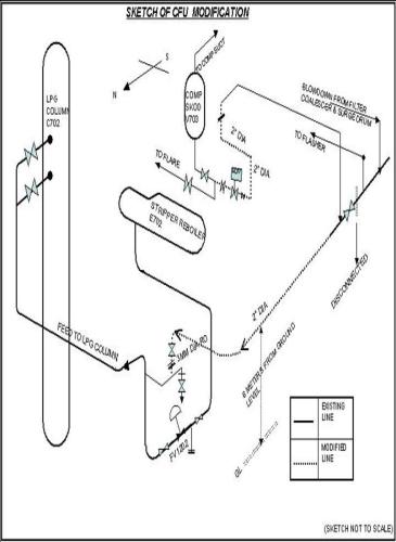
5.0 MODIFICATIONS:
5.1 Modification in the draining procedure of Compressor suction KOD (V703) in Trains 72 & 76; (See Annexure II; Figure 5.2)
The flashed vapours from the surge drum V701 and the Offgas from the Stripper Column C701 are combined and compressed. This compressed gas is further sent back to GSU upstream for sweetening as it is sour in nature. Condensable hydrocarbon vapour in the offgas is knocked off in the suction KOD V703 of the Compressor. On actuation of Level high switch LSH1209 in V703, the liquid needs to be drained off into the flare KOD before level high-high switch LSHH1210 is actuated resulting in tripping of the compressor.
In trains 72 & 76 (as shown in the Figure No.5.2) this liquid instead of being drained into the flare line is directed into the LPG Column. The modified drain line from K.O.D joins the feed line to LPG column from stripper reboiler at the downstream of the control valve FV1202. The SDV1104 provided on the drain line has to be opened from the C/R by pressing a push button PB104 provided. After draining the liquid level reaches at a point, actuating LSL1211, which as a result unlatches/closes SDV1104 automatically.
Condensate fractionation unit
6.0 TRIP AND ALARM SETTINGS:
6.1 PRESSURE SWITCHES & ALARMS:
TAG No. | DESCRIPTION | SET POINT Kg/cm2 | ACTION |
PSH1105 | Condensate feed pressure high | 95/59 | Alarm |
PSH1107 | Surge drum pressure high | 81/55 | Alarm |
PSH1108 PSH1109 | Surge drum pressure high-high | 83/59 | Close LV1101 Close LV1106 Close SDV1101 Close FV1101 |
PSL1110 | Surge drum pressure low | 74/44 | Alarm |
PSL1111 | X701A/B out pressure low | 82/54 | Alarm |
PSH1206 | Stripper bottom pressure high | 26/19 | Alarm |
PSHH1207 | Stripper bottom pressure high-high | 28/21 | Close FV1201 |
PSH1208 | V703 Comp. suction pressure high | 25/18 | Alarm |
PSL1209 | V703 Comp. suction pressure low | 21/14 | Alarm |
PSHH1106 | LP steam pr. To E701 high-high | 7 | Close LV1101 Close LV1106 Close SDV1101 Close FV1101 |
PSH1302 | LPG Column bottom pressure high | 11 | Alarm |
PSHH1303 | LPG Column bottom pressure high-high | 12 | Close FV1301 |
Condensate fractionation unit
6.2 TEMPERATURE SWITCHES & ALARMS
TAG No. | DESCRIPTION | SET POINT (oC) | ACTION |
TSL1107 | V701 Inlet Cond. Temp. low | 28 | Alarm |
TSL1108 | Stripper feed temp. low | 22 | Alarm |
TSLL1109 | Stripper feed temp. low-low | 18 | Close LV1101 Close LV1106 Close SDV1101 Close FV1101 |
TSH1110 | V701 Inlet cond. Temp. high | 43 | Alarm |
TSH1111 | Off gas to B/L temp. high | 50 | Alarm |
TSH1216 | K701A Disch. Temp. high | 135 | Alarm |
TSHH1217 | K701A Disch, temp. High-High | 150 | Trip K701A |
TSH1218 | K701B Disch. Temp. high | 135 | Alarm |
TSHH1219 | K701B Disch, temp. High-High | 150 | Trip K701B |
TSL1312 | E704 Outlet temp. low | 205 | Alarm |
TSLL1313 | E704 Outlet temp. low | 200 | Alarm |
TSHH1314 | E705 Outlet NGL temp. high-high | 55 | Close LV1301 Close LV1302 |
Condensate fractionation unit
6.3 LEVEL SWITCHES & ALARMS
TAG No. | DESCRIPTION | SET POINT (mm) | ACTION |
LSH1107 | V701 Level high | 1300 | Alarm |
LSHH1108 LSHH1109 | V701 Level high-high V701 Level high-high | 1400 1400 | Close LV1101 Close LV1106 Close SDV1101 Close FV1101 |
LSL1110 | V701 level low | 250 | Alarm |
LSLL1111 | V701 level low-low | 150 | Trip P701A/B |
ILSH1112 | V701 boot level high | 2000 | Alarm |
ILSL1113 | V701 boot level low | 300 | Alarm |
ILSLL1114 | V701 boot level low-low | 200 | Close SDV1102 Close LV1102 |
ILSH1115 | X701A boot level high | Alarm | |
ILSL1116 | X701A boot level low | Alarm | |
ILSLL1117 | X701A boot level low-low | Close SDV1103 Close LV1103 | |
ILSH1118 | X701B boot level high | Alarm | |
ILSL1119 | X701B boot level low | Alarm | |
ILSLL1120 | X701B boot level low-low | Close SDV1104 Close LV1104 | |
LSH1204 | C701 Level high | 1900 | Alarm |
LSL1205 | C701 level low | 300 | Alarm |
LSLL1206 | C701 Level low-low | 200 | Trip P703A/B (redundant) |
LSH1207 | E702 Level high | 1250 | Alarm |
LSL1208 | E702 level low | 250 | Alarm |
LSH1209 | V703 Level high | 500 | Alarm |
LSHH1210 | V703 level high-high | 1250 | Trip K701A/B |
LSL1211 | V703 level low | 150 | Alarm |
LSH1306 | C702 level high | 2000 | Alarm |
LSL1307 | C702 level low | 200 | Alarm |
LSH1308 | V702 Level high | 900 | Alarm |
LSL1309 | V702 Level low | 300 | Alarm |
LSH1310 | V708 level high | 1000 | Alarm |
LSL1311 | V708 level low | 150 | Alarm |
LSH1312 | V709 level high | 1000 | Alarm |
LSL1313 | V709 level low | 150 | Alarm |
LSH1801 | V792 level high | 2200 | Alarm |
LSL1802 | V792 level low | 250 | Alarm |
LSH1803 | V791 level high | 500 | Alarm |
LSL1804 | V791 level low | 200 | Alarm |
Condensate fractionation unit
7.0 OPERATIONAL TIPS:
Process Objectives:
To strip Hydrogen sulphide content from the condensate received from the offshore gas/condensate supply through slug-catchers at Hazira Gas terminal.
To fractionate the condensate into LPG & NGL.
Principal of Operation:
To achieve proper separation of lighter and heavier hydrocarbon through vapour-liquid equilibrium in the fractionation columns by establishing desired temperature profiles consistently.
Process Variables:
Operating variables affecting the stripping of H2S and fractionation of condensate are tabulated below;
A) Stripper Column C701:
VARIABLE | DESIGNED OPERATING VALUE/RANGE | COMMENTS |
Feed Rate | 30-75 m3/hr | Higher feed rates will cause:
|
Feed Temperature | 35-38 oC | Higher feed temp. leads to;
Lower feed temp. leads to:
|
Condensate fractionation Unit
Operating Pressure | 18 to 19 Kg/cm2 | Higher pressure leads to:
Lower pressure leads to:
|
Reboiler vapour outlet temperature | 130-140 oC | Higher temp. leads to;
Lower temp. leads to;
|
H2S Content of bottom liquid | < 4 ppm | Higher content will lead to off spec LPG product. |
B) LPG Column:
VARIABLE | DESIGNED OPERATING VALUE/RANGE | COMMENTS |
Operating pressure | 9.7 Kg/cm2 | Higher pressure leads to;
Lower pressure leads to;
|
Column top Temperature | 58-60 oC | Higher temp. leads to;
Lower temp. leads to:
|
Condensate fractionation Unit
Reflux rate | 1.5 times of LPG product (withdrawl) | Higher reflux leads to:
Lower reflux leads to:
|
Reboiler vapour outlet temperature | 175-185 o C | Higher temp. leads to;
Lower temp. leads to;
|
C) Quality of Products:
PRODUCT | DESIGNED OPERATING VALUE/RANGE | COMMENTS |
LPG: 1. RVP 2. Weathering | 16.5 kg/cm2 at 65 o C -2 to +2 o C |
|
NGL: 1 RVP 2. Weathering | 6.5kg/cm2 at 45 o C 0.5% Mole (Max) |
|
-END OF THE DOCUMENT-